|
July 1933 Radio-Craft
 [Table
of Contents] [Table
of Contents]
Wax nostalgic about and learn from the history of early electronics.
See articles from Radio-Craft,
published 1929 - 1953. All copyrights are hereby acknowledged.
|
While reading through this article
on copper-oxide rectifiers, I am once again reminded of how much we take for granted
the conveniences of electrical test equipment on today's shop benches. The advent
of FET-input multimeters was a huge step forward because the meter input impedance
is so high that it has practically no impact on the circuit being measured. Prior
to that, most simple meters drew their power from the circuit under test, thereby
altering the true value of current or voltage being measured. Of course there were
vacuum tube voltmeters (VTVM) with high input impedances, but few hobbyists or laymen
could afford them. This piece reports on how the advent of a non-tube-based rectifier
permitted alternating current (AC) measurements to be made by DC-driven d'Arsonval
meter movements so as to not excessively load the circuit being measured.
Rectox
meters had the rectification components and calibration built in, and while still
more expensive than circuit-driven meters, were much more affordable than other
types. Today, of course, you can get a free DMM with more accuracy and greater functionality
than any 1930s era multimeter at
Harbor Freight just by handing the clerk a readily available coupon.
Applications and Characteristics of Copper-Oxide Rectifiers
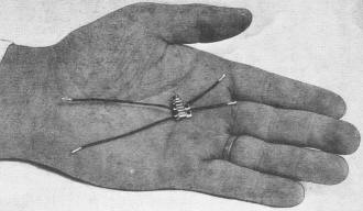
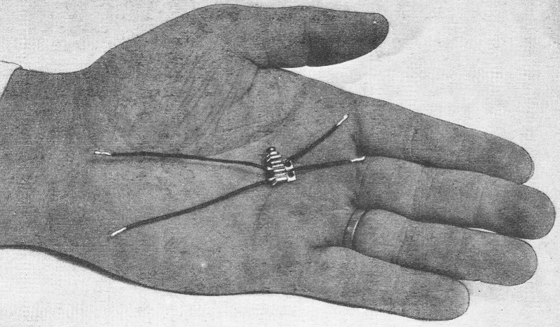
An actual photograph illustrating the size of the rectifier unit.
B.R. Hill*
*Meter and Instrument Section, Westinghouse Electric and Mfg. Co.
The copper-oxide rectifier is used so extensively in modern test equipment, and
is so little understood, that the editors are pleased to present this excellent
discussion of the uses and limitations of copper-oxide rectifiers.
The practical measurement of alternating currents has, heretofore, been made
by three types of instruments: the electrodynamometer, the repulsion or attraction
iron vane type and thermo-couple-d'Arsonval type. The electrodynamometer type has
a system of stationary and moving coils without iron in the magnetic circuits; the
repulsion iron-vane types have a stationary coil, a movable vane and a stationary
vane. Some types of this movement consist of a stationary coil and a single, movable
attraction iron vane. In the thermo-couple-d'Arsonval type - a thermocouple is heated
by the alternating current and the resulting thermo-emf is measured by a d'Arsonval
instrument. Now we have a fourth, practical A. C. instrument known as the Rectox
type. It consists of a copper-oxide rectifier and a d'Arsonval type of instrument.
The alternating current is rectified and then measured by the ordinary direct-current
d'Arsonval instrument.
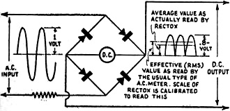
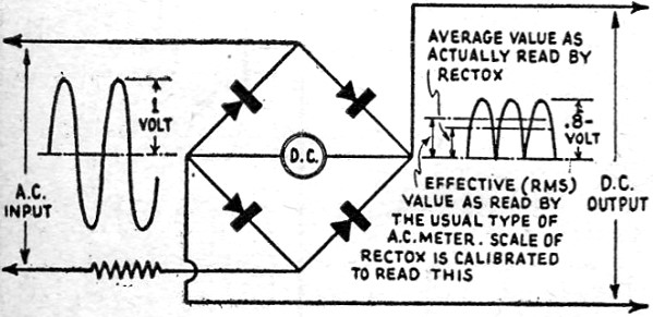
Fig. 1 - A simple sketch showing the connections and calibration
of Rectox instruments.
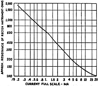
Fig. 2 - A curve showing the relation between the resistance
of and the current through Rectox meters.
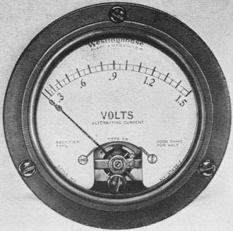
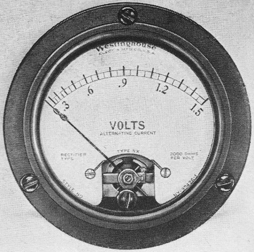
Front view of the new instrument.

Rear view showing the rectifier.
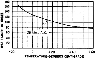
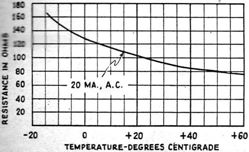
Fig. 3 - Curve showing the relation between the resistance
and the temperature of copper-oxide rectifiers.
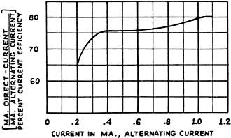
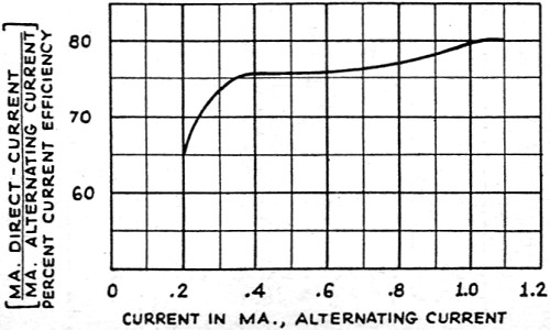
Fig. 4 - An interesting curve showing the relation between
the efficiency and A. C. input.
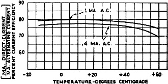
Fig. 5 - Another curve, which shows the relation between
the efficiency and temperatures of copper-oxide rectifiers. Note the variation with
current.
The energy consumption, or the power required to operate the pointer; in the
previous types of alternating-current instruments is much more than that required
for direct-current instruments. This is because, in a direct-current instrument,
the magnetic field is supplied from a strong permanent magnet, permitting a comparatively
small current in the moving coil. The higher energy consumption of alternating current
instruments has been an application handicap for a long time, especially, where
the energy consumed by the instrument would seriously change the circuit conditions,
particularly in radio measurements. The Rectox instrument has successfully solved
this problem by embodying the high sensitivity features of the d'Arsonval type in
an alternating-current instrument.
Rectox Rectifier
The rectifier used in the Rectox instrument is a product of Westinghouse engineering
and research. It is specially designed for instrument use, the requirements of which
are considerably different from the usual well known battery charging applications.
The rectifier units are plates of copper which have been oxidized on one side.
Copper, when oxidized on its surface, has the peculiar property of rectification,
allowing current to flow much more readily from the oxide to the copper, than from
the copper to the oxide. The copper plates are assembled and held firmly in place,
under constant pressure, by a sturdy clamp, and the entire unit is impregnated to
seal it from moisture and corrosion. It is interesting to note that the size of
these rectifier units is considerably smaller than the usual battery-charging unit.
The relative area of the copper oxide plates greatly affects the performance of
rectifier instruments; the proper area of plate has been determined after exhaustive
research.
The assembly of copper plates is made to give full-wave rectification for all
instrument applications. This is accomplished by assembly of the plates into four
sections in reverse order and connecting to the instrument as shown in Fig. 1.
Operating Characteristics
The Rectox instrument has certain characteristics which makes its application
to measurement of alternating currents somewhat critical. For this reason its operating
characteristics should be carefully considered in any application for measurement
purposes.
This class of instruments differs from the usual alternating-current types in
that the torque and deflection are proportional to the first power of the current.
Therefore, it measures the average value and not the effective value of the alternating-current
wave. The scale is, however, calibrated to read effective, or root mean square,
values of a pure sine wave. Consequently, such instruments read correctly only on
sine waves and have serious errors on other than sine wave forms. These errors can
be compensated for in readings, provided the wave form is known from which a correction
factor can be applied; or, the instrument may be calibrated on the wave form with
which it is used.
The resistance of the Rectox is a function of the current flowing. This characteristic
is shown in Fig. 2. When a rectifier-type milliammeter is connected in a circuit,
it affects the circuit conditions because of its added resistance, like any other
instrument; also the changes in the circuit depend upon the value of current passing.
This disturbance of the normal circuit must be recognized if the milliammeter resistance
is a large percentage of the total circuit resistance. If the circuit resistance
is relatively high, then this change will result in negligible effects. The instrument
always correctly indicates the actual current passing through the circuit; but the
magnitude of the current may depend upon the non-linear value of the instrument
resistance. (The actual resistance of the Rectox varying with current. - Editor)
The readings of Rectox instruments are quite free from frequency errors. The
reading may be expected to decrease about 1/2 per cent per kilocycle up to 35,000
cycles, where different conditions occur. Because of capacity effects, this type
of instrument is not recommended for radio-frequency measurements. It is, however,
reasonably accurate throughout the audio frequency bands.
The effect of current upon the resistance of a rectifier unit has been previously
discussed, but the copper-oxide unit also has the property of changing its resistance
with temperature; and, furthermore, the amount of change due to temperature depends
on the amount of current passing. Temperature resistance curves are shown in Fig. 3.
We have, therefore, a very complex .relation between current, temperature, and resistance.
As a result of these conditions, a great deal of skill is required in designing
a Rectox instrument to prevent errors arising from temperature changes.
Tests show that the effective resistance of a copper-oxide rectifier decreases
as the temperature increases. Therefore, if a rectifier instrument should be used
as a low-range voltmeter, without suitable temperature compensation, the voltmeter
might read as much as 20 or 25 percent high at a temperature of 40°C. It is
for reasons of this kind that little success has been met in trying to adapt Rectox
units to standard direct-current instruments. Much better results have been obtained
by use of specifically designed combinations of instrument and rectifier, in which
proper temperature compensation has been developed.
Like all devices of its kind, the efficiency of the copper-oxide rectifier is
less than 100%; in other words, if 1 milliampere A.C. is passed through it, the
resulting rectified current available for operating the indicating instrument is
usually 8/10 of a milliampere, or less. The typical current efficiency curve for
a rectifier instrument is shown in Fig. 4. Furthermore, the current-efficiency
ratio (D.C. current output divided by A.C. current input) is affected to some extent
by temperature and, also, by the absolute value of current flowing. Fig. 5
shows this characteristic. This again results in a complex situation involving temperature,
current, and efficiency; and a simultaneous study of all of these variables is the
only means by which errors from temperature variations can be minimized. For example,
with certain values of current flowing, the efficiency of an uncompensated rectifier
instrument may drop from 80% to 75% during a 40° C. temperature rise. This would
result in lowering the calibration of the instrument 6% at the higher temperature
if no steps were taken to secure temperature compensation.
Summary
The majority of the above discussed errors, characteristic of rectifier instruments,
can be minimized by careful design and by taking advantage of the opposite effects
of certain errors. However, it is important that the instrument be properly designed
to operate with the copper-oxide rectifier. It is therefore, not advisable to try
to apply a copper-oxide rectifier to an existing d'Arsonval instrument which has
not been designed for this application unless changes are made to provide proper
moving coil resistance, temperature compensation, and swamping resistance. If the
errors are properly cared for in the design of a complete rectifier instrument,
reasonable accuracy can be obtained.
The chief advantage of. a rectifier instrument is in its high sensitivity.
By use of the rectifier principle, alternating-current voltmeters may be made with
a very high resistance per volt. Standard voltmeters are available in ratings as
low as 4 volts with a sensitivity of 1,000 ohms per volt, 1.5 volts with 2,000 ohms
per volt, and even 0.5-volt with 5,000 ohms per volt. Below four volts, rectifier
voltmeters should have a resistance of 2,000 ohms and, better still, 5,000 ohms
per volt, in order to properly compensate for the errors discussed above. Milliammeters
and microammeters of low ratings are also available.
Rectifier instruments are rapidly finding their place in the radio field for
the measurement of such quantities as output of amplifiers and oscillators and power
level indicators. The user of these instruments should bear their characteristics
in mind, particularly their accuracy, when used under various conditions. Rectifier
instruments are a valuable contribution to the science of radio and they are continually
finding new uses in this rapidly advancing art. Possibly the further developments
in research and engineering on these instruments will tend to minimize their present
errors and make them still more useful.
Posted July 6, 2022
(updated from original post on 7/28/2015)
|