|
February 1933 Radio-Craft
 [Table
of Contents] [Table
of Contents]
Wax nostalgic about and learn from the history of early electronics.
See articles from Radio-Craft,
published 1929 - 1953. All copyrights are hereby acknowledged.
|
In a continuing effort to provide archival
material for researchers and for anyone seeking information on a particular radio
restoration project, this Radio Service Data Sheet for the Crosley "Chief" Model
132-1* radio from a 1933 edition of Radio-Craft magazine is being posted. An Internet search
will show that there are many people engaging in such activities. Restoring my
Crosley Model 03BC console radio would have been more difficult
if not for others who have done similar work to assist the "community." I generally
despise the phrase "giving back" because it is usually uttered by people that really
owe nothing to anyone, but somehow feel obligated to do so or are conditioned to
automatically say such things. This is a case where I benefitted from somebody else's
work and there is an opportunity to return the favor. * Interestingly, the
RadioMuseum.org website has the Crosley Model 132-1 listed as the "Ambassador." Crosley "Chief" 12-Tube
Model 132-1 12-Tube Superheterodyne Radio Service Data Sheet
(Dual reproducers, class B push-push A.F. power output fed by a class A push-pull
driver stage, meter tuning, A.V.C., tone control, static control.)
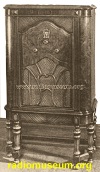
 The Crosley Chief, 12-tube superheterodyne
console model radio receiving set, is the most recent addition to the line. This
receiver incorporates the model 132-1 chassis. Although incorporating. a large number
.of tubes, the power line current consumption is held to a minimum by use of the
new tubes which consume much less current than the older types. The Crosley Chief, 12-tube superheterodyne
console model radio receiving set, is the most recent addition to the line. This
receiver incorporates the model 132-1 chassis. Although incorporating. a large number
.of tubes, the power line current consumption is held to a minimum by use of the
new tubes which consume much less current than the older types.
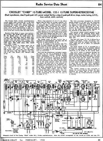
Resistors: R1A; R1B, 1.5 megs. (per section); R2,- 0.4-meg.; R3, 80,000 ohms;
R4, 0.15-meg.; R5, R6, 60,000 ohms; R7, 2,000 ohms; R8, 1 meg.; R9, 7,000 ohms;
R10, 40 ohms; R11, 750 ohms; R12, R13, R24, 0.5-meg.; R-14, R23, 0.3-meg.; R15,
450 ohms; R16, 3 megs.; R17, 30,000 ohms; R18, 20 ohms center-tapped; R19, 3;500
ohms; R20, 6,000 ohms; R21, 10,000 ohms; R22, 5 megs.
Condensers C1 to C4, tuning units; C5 to C8, I. F. trimmers; C9, C25, C26, 0.02-mf.;
C10, C11, C13, C14, C16, C30, C31, C32, 0.1-mf.; C17, C15, 4 mf.; C18, 150 mmf.;
C19, 100 mmf.; C20, C23, 0.006-mf.; C21, C22, C28, 8 mf.; C24, 0.05-mf.; C27, 0.003-mf.;
C29, 12 mf.
With a line potential of 117.5 V. the above figures may be taken as average readings;
for "220 V." sets a line voltage of 235 is taken as standard. Bias (unless otherwise
stated), screen-grid, and plate readings are taken between these tube contacts and
the emitter; bias for V3, V5, V7 to V11, cathode to chassis.
Late chasses of this model have a 1,400-ohm resistor shunted across the visual
tuning meter. Also, these later chasses may have two 1 meg. resistors (total) in
the manual volume control circuit, connected from the moving arms to the ground
ends of R1A and R1B.
The tuning meter of this receiver has a resistance of approximately 440 ohms
and the deflection is approximately 10 ma.
The A. F. output of V6 actuates tube V11 which. in turn, controls the bias on
the amplifier tubes for A.V.C. operation. By manual adjustment of R2 the degree
of background noise is controlled to suit individual preference of sensitivity.
Note that the transformer secondary supplying tubes V1, V2, V3 is bypassed by
a dual-section condenser, C30-C31. Another unusual circuit arrangement is the use
of a double choke coil arrangement comprising Ch1-Ch2. and field coils 1 and 2.
The first two choke coils are connected in the positive high-voltage lead in the
usual manner, while the second two chokes, the field coils of the dynamic reproducers,
are connected as an "inductive voltage divider," one terminal of the two coils in
series being connected to the positive output of the regular filter system, and
the other end being grounded to the chassis; the center-tap of these field coils
supplies voltage to the screen-grids of V1, V2, V 4, and to the plate of V5.
The tone correction furnished by C25-C26 applies equally to V9 and V10, the center-tap
of these two condensers being grounded to the chassis. If any portion of the tone
control R3, C24, becomes grounded the A. F. portion of the receiver will become
inoperative as the entire tone control operates at the potential of the plates of
V7, V8.
The manual volume control operates in the input circuit of the push-pull driver
stage, V7-V8. The two sections of this volume control, R1A, R1B, operate simultaneously
as a dual unit.
The first A.F. stage, V7, V8, is driven by a so-called split-diode circuit furnishing
A.F. voltage from both the cathode and plate circuits, which are out of phase (in
push-pull relationship) .
The input circuit of V1 is preceded by a band-selector which must be carefully
aligned in order to maintain the required degree of selectivity at all points in
the tuning band.
The A.V.C. action is obtained through the voltage drop across resistor R4. There
is an initial current flowing through this unit and the 5 meg. grid leak, R22, furnishing
a normal bias for the R.F. and I.F. stages. The A.V.C. tube V11 is delayed by means
of a positive potential on the cathode of about 60 V. When an R.F. signal of sufficient
intensity is applied to make this A.V.C. tube (D.C. amplifier) draw plate current,
its plate current also flows through R4 and furnishes an additional A.V.C. bias.
The "static" control is also connected to change the current flowing through
R4, thus changing the initial bias on the controlled tubes, so that the overall
sensitivity of the set is reduced.
Posted May 17, 2022
(updated from original post
on 3/24/2015)
|