|
November 1937 Radio-Craft
 [Table of Contents] [Table of Contents]
Wax nostalgic about and learn from the history of early electronics.
See articles from Radio-Craft,
published 1929 - 1953. All copyrights are hereby acknowledged.
|
Not many people are still using
analog meters for making voltage, current, resistance, and power measurements these
days; however, for those who are and even for those using digital readout meters,
there are valuable lessons to be learned from this article on factors that can affect
the accuracy of your measurements. Whenever you make a measurement with any kind
of instrument, the first step to take in minimizing the chances of inaccurate readings
is to be certain the instrument is in good working order and is known to be reasonably
accurate. If it is battery powered, know that low battery voltage can cause erroneous
readings in both analog and digital meters, so beware. If you are making a measurement
to verify a known entity and the reading is correct, then there is little reason
to suspect that anything is wrong with your meter. If a reading is way off from
what you expect to see, then verify the accuracy of your instrument before going
any further lest you waste valuable time and possibly cause harm to yourself and/or
the circuit you are testing. Here is
Part
1 of this series.
How Dependable Are Your Meter Readings?
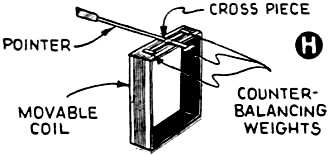
Fig. 2H - Moving-coil and counterweight assembly.
A nationally-known writer on technical radio subjects presents to Radio-Craft
readers many heretofore unpublished facts, of importance to all radio men, concerning
test meters.
Alfred A. Ghirardi
Part II
There are several inaccuracies which are apt to creep into measurements made
with electrical instruments simply because of the way the instrument is used, or
the conditions under which the measurements are made. Errors which may be present
when a particular instrument is used for one measurement may not occur when it is
used again under different operating conditions - and vice versa! Some things to
watch for will now be pointed out.
(L) Unbalancing.
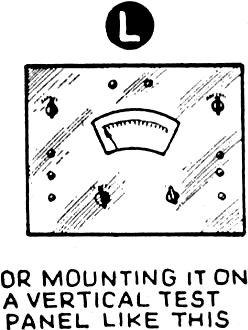
Fig. 3L - Meter error due to vertical mounting.
In the construction of most movable-coil type meters, an effort is usually made
to balance the assembly of movable parts (consisting mainly of the movable coil
and the pointer) so that their position is not affected by gravity - i.e., so the
meter will read the same no matter what position it is tilted to, or placed in.
To accomplish this, small counterbalancing weights (see Fig. 2H) are placed
at the two ends of a cross-piece (which is at right angles to the pointer) and one
is placed on the rear end of the pointer (as illustrated).
Since exact balancing necessitates rather precise and tedious adjustments in
the positions of these weights, many meters leave the factories in a slightly unbalanced
condition. Others become unbalanced by jars and knocks which they receive during
shipment and subsequent use.
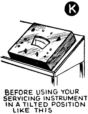
Errors (generally very small) are most likely to make their appearance when the
instrument is tilted and used in a position other than that in which it was originally
calibrated (portable instruments are generally factory-calibrated with the scale
and pointer in a horizontal position).
An instrument intended for use with its pointer and shaft in a horizontal position
should not be used in a tilted, or vertical position until you have assured yourself
that any errors so introduced will be negligible. This applies especially to meters
which are to be used in portable test instruments, and also to those which are mounted
vertically on shop test panels.
The author has checked a representative group of servicing meters, and finds
that the errors in some of them are increased by as much as 5 per cent (making their
total errors around 7 per cent) if they are read while in a tilted or vertical position.
This is a fact which most Service Men fail to appreciate, since they always place
the meter in whatever position they find it most convenient to read, without regard
to possible "unbalance" errors.
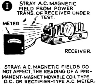
Fig. 3I - Meter errors introduced by stray AC magnetic fields
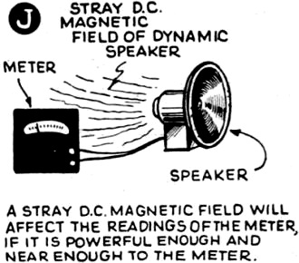
Fig. 3J - Meter errors introduced by stray DC magnetic fields
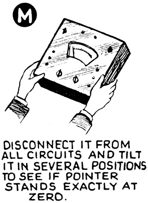
Any instrument may quickly be checked for possible "unbalance" by disconnecting
it from all circuits and tipping it to a position Bay 30 or 45 degrees from the
horizontal (or to several extreme positions ). Notice if this causes considerable
variations in the "zero" position of the pointer. If it does, the instrument is
"unbalanced" and had best be used only in the "normal" position (with both scale
and pointer horizontal). (See Fig. 3, sections K, Land M.) A perfectly-balanced
instrument should show the same "zero", no matter in what position it is placed;
and of course may be used in any position.
(M) Stray Magnetic Fields.
The effect of a stray magnetic field upon the indications of a permanent-magnet
moving-coil type instrument depends upon the nature of the field and its strength.
A stray field due to an alternating current (see Fig. 3I) will have no perceptible
effect on the reading of the instrument, unless it is so strong that it is able
to demagnetize the permanent magnet to some extent, and thus cause the instrument
to read low. Since alternating fields of such strength are rarely encountered, the
Service Man need have no concern about them.
A direct-current magnetic field (such as that produced by an open dynamic speaker,
see Fig. 3J), will affect the indication of a permanent-magnet moving-coil
type instrument if it is sufficiently powerful. Such fields change merely the strength
of the magnetic field in the air gap of the instrument, but not its distribution.
The resulting error will therefore be a constant percentage of the indication of
the instrument, so long as the disturbing field is constant in amount and direction.
The Service Man should therefore be most careful about the use of his instruments
in locations where stray powerful magnetic fields exist.
If a portable instrument; must be used in a place subject to a strong stray field,
the average value of two readings should be taken, the instrument being turned 180
degrees about the axis of rotation of the moving element for the second reading.
Or, the instrument may be placed with its magnetic field at right-angles to the
direction of the stray field, the latter being determined by means of a small magnetic
compass. It is better, of course, to avoid, insofar as possible, exposing instruments
to stray fields.
(N) External Temperature Errors.
Change of external temperature produces various effects on the parts of an instrument
- and these effects differ widely in magnitude.
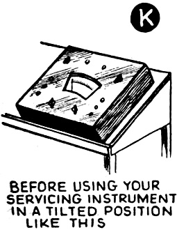
Fig. 3K - Meter error due to angled mounting.

Fig. 3M - Meter error due to tilting.
For example, increase of temperature will cause linear expansion of the metal
parts, increase of resistance of the current-conducting parts, change in elastic
force of the springs, change in operating characteristics of meter rectifiers, etc.
However, the design of modern high-grade instruments has been so well perfected
that the errors due to these effects have been minimized - often by deliberately
balancing one error against another of the opposite sense, resulting in cancellation
of the original error.
The result is that the errors caused by those ordinary room temperature variations
which are encountered in practice in temperate climates are negligible and need
cause no concern. Of course, if electrical measuring instruments are used under
unusual conditions of extreme heat or cold outdoors, their readings will be in error
and suitable corrections should be made if accuracy is essential. However, the radio
Service Man rarely has occasion to make measurements under such abnormal conditions.
It should also be understood that contact resistance in switches, pin jacks and
test prods sometimes results in errors, although these are only large enough to
cause trouble in very low range ohmmeter circuits. In hot, humid climates, certain
metals corrode very fast and if erratic readings are observed under these conditions,
suspect "contact resistance." The remedy? Wiping of all open contacts with a piece
of heavy canvas, and cleaning all tips with very fine sandpaper or an ordinary eraser.
Most rotary switches have "self-wiping" contacts and these may be cleaned by rotating
the control knob through 8 or 10 revolutions.
(O) Instrument Alters Circuit Conditions.
Since the function of an ordinary meter is merely to measure the current, voltage.
or resistance of a circuit, it should not alter or influence the circuit into which
it is connected in any way which would cause an inaccurate or fictitious reading
to be obtained.
So many excellent discussions of this source of error have appeared in radio
magazines and books, that little need be said about it here, except to caution Service
Men to be sure to make all voltage measurements on receiver circuits with sensitive
voltmeters having sufficiently high resistance values so that very little change
in the voltage being measured will be caused by the "shunting" effect of the voltmeter.
This is especially important when checking voltages in high-resistance A.V.C. circuits.
A good working rule to remember when using a voltmeter is that: the resistance
of the voltmeter (for the particular range employed) should be at least 10 times
the resistance of the circuit across which if is connected when making the voltage
measurement. Practical portable instruments having a D.C. sensitivity as high as
20,000 ohms/volt are now available in commercial test instruments.
(P) Quantity Under Measurement Fluctuating.
If the quantity under observation varies in value while the meter is being read,
it is likely that the reading will be in error due to the difficulty of accurately
determining the exact correct position of the pointer.
For example, this condition is likely to occur when checking currents or voltages
in a receiver which is connected to a power line whose voltage fluctuates. Of course,
measurements made under these adverse conditions may be very inaccurate - due to
no fault of the electrical measuring instrument! They should be made as carefully
as possible - due allowance for the possible inaccuracy being made when interpreting
the receiver circuit conditions from them.
(Q) Pointer Position Read Inaccurately.
The accuracy of a measurement made with electrical indicating instruments always
involves the personal element, over which the instrument maker has no control. No
matter how good the inherent accuracy of the instrument is, there is always a certain
amount of error introduced by the observer who does not read the exact position
or indication of the pointer correctly. Of course. the error of reading is influenced
by the size and shape of the pointer, the lighting conditions, the angle at which
the pointer is read, the position of the pointer with respect to the extremities
of the scale division, the care and skill of the observer, and the steadiness of
the quantity under measurement (for the present, we will assume that the quantity
under measurement, and the pointer, are perfectly steady). Let us analyze these
separately.
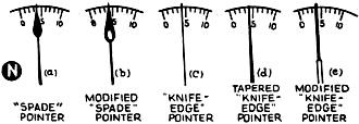
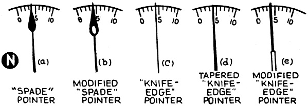
Fig. 3N - Meter pointer design evolution.
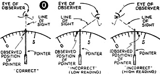
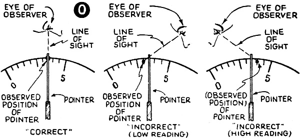
Fig. 3O - Meter errors introduced by parallax.
Pointer Design.
Test instrument manufacturers have given considerable thought to the design of
the pointers used on their instruments, in an effort to reduce observational errors.
The evolution of pointer design is shown by the illustrations in Fig. 3N.
The rugged, but more or less heavy spade pointer shown at (a) was used in the
earlier type instruments because its rugged body is not easily bent when the meter
is overloaded and the needle is "slammed" or "pegged", Also, because of its large,
black surface area, it is more easily followed under the poor lighting conditions
which are encountered in some locations. However, because of its "bluntness", its
position on the scale cannot be read as accurately as can the position of the thinner
types of pointers which have now become more popular. The spade pointer is still
used, however, on electrical measuring instruments whose inherent accuracy is not
very high anyway, on instruments which must be read under poor lighting conditions,
on switchboard type meters which must be watched or read (not accurately) from a
distance. etc. By cutting out the center of the "spade" pointer, as shown at (b),
its weight is decreased without materially decreasing its ruggedness. However, the
objection regarding difficulty in reading its position accurately still holds.
At (c) we have the true knife edge pointer, which is used to some extent on test
instruments. Its advantage lies in the fact that since it is very thin, it enables
closer readings, to be taken. However, "knife edge" pointers are more difficult
to follow in bad light than "spade" pointers are; and, since they are less rugged,
they are much more easily bent when "slammed"
The tapered "knife edge" or "sword" pointer shown at (d) represents one attempt
to maintain the observational accuracy of the true knife edge pointer while adding
more ruggedness to it by reason of its tapered shape. This type is now being used
on some radio test instruments. Another variation of the knife edge pointer which
has been adopted by several of the leading test instrument manufacturers is shown
at (e). Since this has a rugged body like the old spade pointer, it has good visibility
even in poor light; and it is not easily bent when "slammed" against the stop during
overload. The part of the pointer which rests over the scales is a flat, thin, "knife
edge" to make accurate reading possible. Knife-edge pointers such as these help
a great deal in reducing observational error in reading the pointer position.
(R) Parallax Error in Reading Pointer Position.
Even though the instrument manufacturer has been careful to provide the instrument
with a pointer designed for accurate reading, the observer may introduce an error
in reading its position if he is not careful. The illustrations in section O of
Fig. 3 show how this may happen.
When reading the position of the pointer of any indicating instrument, the person
usually closes one eye and "squints" through the other. He should place his head
in position, so that his open eye is directly over the pointer. Then his line of
sight will be through it, and exactly at right-angles to the plane of the scale,
as shown at the left. The reading taken will then give the correct position of the
pointer.
If the eye position is to the right of the pointer, as shown. the pointer position
will be oblique. and the pointer position will be read inaccurately ("low" reading).
On the other hand, if the eye position is to the left of the pointer, as shown,
the line of sight will be read "high". (This type of observational error is commonly
known as parallax.) Therefore, a good rule to follow when reading meter indications
is always to place yourself directly over the meter and look directly down on the
pointer (if the meter is flying flat). If the meter is in a vertical position, place
yourself directly in front of it, and look directly at the pointer. If the pointer
happens to lie between 2 divisions on the scale, estimate its correct position as
nearly as possible.
In some types of more precise instruments. possible observational errors due
to "parallax" are reduced by the use of a thin mirror which is usually cemented
to the scale card and located alongside the scale under the pointer. The image of
the pointer reflects in this mirror. Whenever a reading is to be taken, the observer
shifts his head position until the pointer is seen directly over its image in the
mirror (so the pointer hides its image from view). He then knows that he is looking
straight down onto the pointer and thus will avoid parallax errors.
If a reasonable amount of care is taken, it is possible for a skilled observer
to read the scale position of a knife-edge-type pointer to within 0.005-inch of
its true value, when a mirror is present to avoid parallax. Of course. the accuracy
of reading obtained in practice depends upon the lighting conditions, the eyesight
condition of the person. and the care exercised.
(S) Pointer Deflection Fluctuating.
If the quantity under observation varies in value while the meter is being read.
it is difficult to accurately determine the exact correct position of the pointer.
Under these adverse conditions, a fairly large observational error is likely to
be made. (This was discussed in part [P] of Section [3].)
Read Part III of this article; it will discuss Inherent Meter Accuracy (or inaccuracy).
The author of this vital article is also author of "Radio Physics Course," "Modern
Radio Servicing," and "Radio Field Service Data.," books - all valuable contributions
to the field of literature for the practicing radio Service Man.
Posted September 13, 2022
(updated from original post
on 11/8/2015)
|