|
September 1935 Radio-Craft
 [Table of Contents] [Table of Contents]
Wax nostalgic about and learn from the history of early electronics.
See articles from Radio-Craft,
published 1929 - 1953. All copyrights are hereby acknowledged.
|
We tend to take for granted
"standards" that have been in place and working well ever since they were instituted
long ago. Some - maybe most - standards evolve over time with user preferences driving
the end result; they tend to continue evolving. Examples include keyboard layout,
advertising and product color selection, and test instrument front panel configurations.
Other standards are driven by technology improvements. More and more often it seems,
standards are being set by industry groups that want to assure interoperability
and exchangeability amongst products and users. Often this kind of standard is driven
by government imposed regulations. Wireless communications is a prime instance of
the latter. This article is an example of a combination of standards motivators
since it considers user experience preferences with scientific research to determine
how best to implement a radio tuning dial. This was done nearly a century ago when
a large portion of the world's population had never touched a radio dial or turned
the knob of an instrument. Some of the findings were widely adopted, but looking
at the huge number of radio that were produced since 1935 when this article appeared
in Radio-Craft magazine shows that no recognizable standard ever was stuck
to for radio dial layout.
Design Problems of Tuning Dials
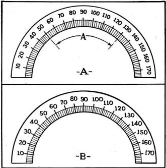
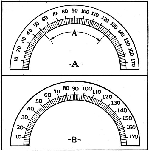
Fig. 1 - The wrong (A) and right (B) way to number the tuning dial.
By Wilhelm E. Schrage
"Short-sightedness" is not only an ocular disability - it is, according to the
author, also a manufacturers' ailment!
While tremendous strides have been made in radio receiver parts during the last
few years, constructors have given little attention to tuning dials. That such is
the situation can easily be seen by comparing present European dials with those
of American design. Our constructors seem to prefer the old orthodox "electric meter"
dial in use since 1850! More attention is today given to tuning dial decoration
than to actual scale design. As a matter of fact, the present decoration fad is
being overemphasized so much in many instances as to occupy twice the square-inch
area allotment given to the really useful part of the dial - that is, the scale!
It is high time for the radio engineer to break down the dictatorship of the
cabinet designer, and demand a tuning dial which will allow the listener to discard
the "microscope or magnifying glass" so often needed for selective station tuning
(especially on short waves). Modern tuning dials serve to promote activity for the
oculist rather than to serve as a restive agent for the eye of the radio listener.
The present high-fidelity movement toward fulfilling all the wishes of the musical-trained
ear, should be accompanied by equal solicitude on the part of the engineer toward
the welfare of the eye.
The average radio buyer merely asks for faithful speech and music reproduction,
together with a simple method of station tuning. In order to learn the kilocycle
indication for tuning in the desired station it is necessary today for the listener
to refer to the radio program column in a daily newspaper or magazine. However,
after "finding the proper kilocycle indication, and dropping the last cipher," the
listener then must go through body exercises comparable to his daily dozen in order
to adjust the tuning dial. Such body and head movements, often consist of a 50 degree
banding motion to the right or left, the angle depending upon the type of dial in
use.
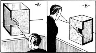
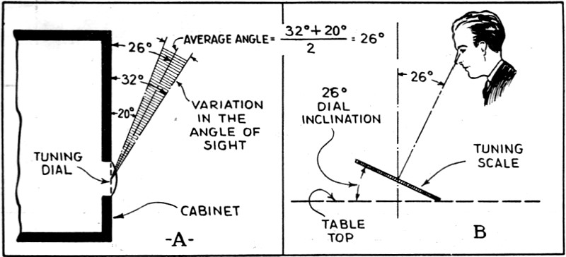
Fig. 2 - Poor (A) and good (B) dial angles.
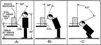
Fig. 3 - How we look at the dial.
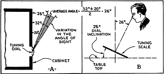
Fig. 4 - Finding "best" angle.

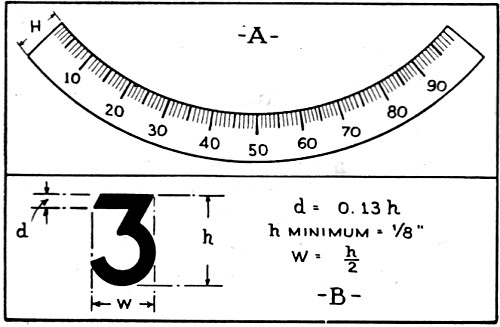
Fig. 5 - Finding "optimum"-size numbers.
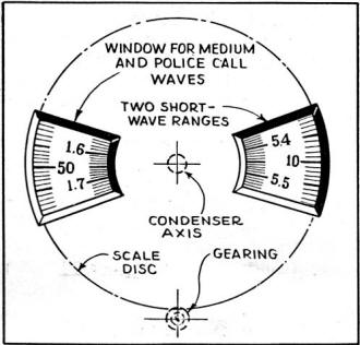
Fig. 6 - 4-range "propeller" dial.
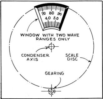
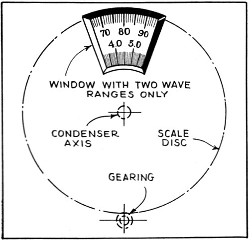
Fig. 7 - 2-range window dial.

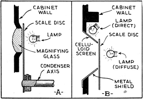
Fig. 8 - Two types of good dial lighting.
If the set dial is furnished with inclined numerals as in Fig. 1A, only
the part indicated as "A" can be read without bending the head to right or left.
Thus, about 50 per cent of the scale is ineffective insofar as ease of reading is
concerned. Yet, surprising as it may seem, more than 22 per cent of American radio
sets are equipped with this type of dial.
The same dial would be easier to operate if the numerals were horizontally arranged
as shown in Fig. 1B. A scale designed in this manner may be used over the
entire semi-circle. The suggested dial type must be of slightly wider diameter than
those in present use; however, this demands only a cut-down of the decoration area
customary at present.
Another important point concerning the dials used today, (and one which is worthy
of change) is that of dial direction. The average table height is 31 ins., hence
the tuning dial height averages 38 ins. above the floor, as shown in Fig. 3A.
while the average eye is 64 ins. above the floor. At present it is custom to use
the upper part of the circle for the tuning dial as shown in Fig. 2A, requiring
the listener to stoop to a position which places the eyes on a level with the table
top. Apparently the only reason for this archaic design is because of similar "electric
meter" style in dials having been used by our grandfathers since 1850.
However, the use of the lower part of the circle as shown in Fig. 2B, for
a tuning dial with an inclined scale will not give the desired satisfaction unless
such inclination is to a certain degree accommodated to our eyes. An example of
"unaccommodation" is shown in Fig. 3A, in which a radio set is standing on
a table (average height 31 ins.), and with its tuning dial 7 ins. above the top.
In this case if the radio receiver has sufficiently large numbers, and if the radio
listener is long-sighted his eye will look upon the dial at an angle of 32 degrees.
Should the listener be near-sighted (see Fig. 3B) the angle under the same
conditions will be only 20 degrees. These angles of sight will be obtained if the
radio listener is of average height, (eyes 64 ins. above the floor). Small deviations
of a few inches more or less will not make a very great difference because of the
comparatively short distance involved.
According to Fig. 4A. we have a variation in the angle of sight between
32 degrees and 20 degrees. The average angle of sight would then be:
(32° + 20°) / 2 = 26°
Upon drawing this angle in Fig. 4B. we find that the accurate inclination
for our tuning scale should be 26 degrees to the table top.
However. a dial constructed according to Fig. 4B, with an inclination of
26 degrees will not fulfill its purpose if the numerals are not of a certain size.
Since the radio listener does not like to carry a chair to the receiver, there to
remain sitting until he has found the desired station, it is necessary for him to
make some unpleasant gymnastic exercises (as shown in Fig. 3C) to tune in the
desired station, because of insufficiently large numerals on the scale. This example
shows the importance of providing tuning dials with large numerals.
In order to be of greatest ease to the eye the oculist has set the extreme minimum
size of tuning dial numerals at 1/8-in. The numerals should be simple in design
and the size of "d" and "w" (see Fig. 5B) should not be smaller than:
d = 0.13h
w = h / 2
Many dial constructors claim that due to the small size of the dial it is impossible
to use numerals of this size. This problem, however. like most, can be solved. The
simplest method to obtain sufficient space for use of larger numerals is that of
constructing scales with a circle segment of 90 divisions, 100 divisions, or 110
divisions only as in Fig. 5A. This type of scale, with numerals printed horizontally,
affords a full sight over the full segment without bending the head to the left
or right. The distance between the scale divisions will become much greater, serving
to give an effect of "greater" receiver selectivity. Division lines may then be
employed with a thickness greater than those now in use, offering not only eye relief,
but also helping to cut down adjustment expenses, and last but not least the "apparent
selectivity" is greatly enhanced.
If the width "H" of the scale shown in Fig. 5A, is of sufficient size it
is relatively easy to divide the dial into several parts; this will afford sufficient
space for several wave ranges. Dials of the suggested type can be designed to meet
any demand, and with the right inclination and proper size of the numerals it should
prove to be a first-class advertising and selling argument. What has been said about
the semi-circle dial applies also to dials well known under the designations "full
vision," and "airplane type," since for scale readability it makes little difference
whether the dial is designed in the form of a circle or a semi-circle.
Many of the full-vision dials in use today are badly constructed - over a space
of a few square inches we find three or four wave ranges, so that the poor radio
listener needs a guide to find his way through this labyrinth! From the point of
usefulness, the dial design shown in Fig. 5A is best. However, if the cabinet
designer believes at present that a full circle is desirable in order to secure
some aesthetic effect. he should use a circular dial such as shown in Fig. 6.
The dial shown in Fig. 7, often used today, utilizes only 180 degrees of the
full circle; an expensive gearing is necessary if we wish to use the full 360 degrees.
If there is a need for several wave ranges, and if numerals of a larger size are
desired. more space must be given to the window.
An "Engineered" Dial
All these disadvantages can be avoided by use of what might be termed a "propeller"
scale (see Fig. 6.) Two small windows are used one for the medium waves, the
two together for police calls and the other one for two short-wave ranges. By use
of a wave-range switch ganged with a multi-contact pilot-light switch, the correct-range
windows can be respectively illuminated. The numerals are horizontal in any position
of the scale, and if we use slender figures their size can be quite large without
enlarging the disc diameter. Such propeller-like dials are very useful for midgets
because they do not require a great deal of space, and so give the radio listener
the full benefit of a good, legible dial; the dial can be made still more legible
if a magnifying glass ("bullseye") is arranged in the window frame as shown in Fig. 8A.
The indicator line can then be directly engraved into the glass.
If a good legible dial is desired, an important factor is the illumination of
the scale especially as regards the color and material carrying the scale divisions.
It is essential for the scale to be sufficiently well illuminated but not so strongly
as to partially blind the eyes. One illumination system is shown in Fig. 8B.
The front and the rear of the dial are illuminated. By using two small, low-voltage
lamps instead of a single large one, a very pleasing effect can be obtained.
Color is another important consideration in dial design. At present most scale
discs are made of celluloid or some similar material showing a brownish cast. Some
manufacturers use this material for scale discs only because of low cost, yet no
advertising manager would use a transparent sign of such color for he realizes the
difficulty that would be encountered in reading and illuminating it. Only a white
material printed with black divisions and numerals should be used for the disk.
It might be useful to use blue numerals for the police-call range, and red ones
for the short-wave range. The use of white, transparent figures and divisions on
a black background is not be recommended, for a dial of this type has a tendency
to dazzle the eye. "White on black" may, however, be used for large dials with a
few divisions and numerals only - for example, in airplanes to avoid annoyance to
the pilot who must look through darkness, but not for tuning dials on home radio
sets. No electric meter manufacturer today would use these "negative" dials; ask
any power station engineer whether he prefers a scale having a negative design and
the answer will be "No!"
Dials made by stamping, after the first few hundred run off no longer show the
clean-cut appearance of the earlier dials. A much better method of dial manufacturing,
then, is that of photo-lithography. Scales made by the latter method have the distinctive
advantage of uniform, clean and clear-cut divisions.
However, by the use of front illumination together with a magnifying glass (a
third manufacturing method) the "photo-etched" type of dial is very satisfactory.
These dials, which are opaque, are made of a white metal having a semi-polished
surface. They are not costly if identical dials on quantity basis are needed and
they give the radio cabinets a more expensive appearance.
Posted July 10, 2024
(updated from original post
on 8/11/2016) |