Design of Radio-Frequency Transformers
|
|
Open up a radio transceiver chassis that operates below 300 MHz (VHF and lower), particularly one built before the advent of highly integrated circuits, and you will almost certainly find many transformers and inductors. Without the advantage of using microstrip type distributed impedance matching, the use of wire-wound transformers and inductors is your only option for tuning filters and implementing interstage impedance matching. In the days of vacuum tubes in all stages of a transmitter and/or receiver, transformers were found in every stage from baseband through RF. Knowing how to design and build efficient transformers was essential to proper operation. This circa 1931 article provided a basis for understanding the science of mutual inductance and magnetic coupling. Design of Radio-Frequency Transformers As modified by the problems which have been introduced by the multi-stage screen-grid amplifier By Sylvan Harris From the viewpoint of the designer of a radio-frequency amplifier which is to be part of a radio receiver, when he has once determined the number of tuned and untuned stages he wants to use and the amount of amplification he must have, there remain really only three problems that he must solve. Assume therefore, that the circuit arrangement of the amplifier is settled and the particular tubes chosen: the designer then must determine - (a) the proper voltages to use on the tubes and the manner of obtaining these from the power-pack; (b) the system of controlling volume and the location of the volume-control elements in the circuit; (c) the actual design of the radio-frequency transformers,
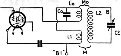
Fig. 1 - In the standard screen-grid amplifier stage, the high plate resistance of V1 necessitates a high impedance in L1B and, therefore, loose coupling into the tuned circuit L2B-C2.
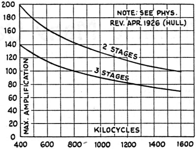
Fig. 2 - The theoretical limit of screen-grid amplification; on the basis of 1000 micromhos of mutual conductance, and 0.02·mmf. grid-plate capacity in the screen-grid tube.
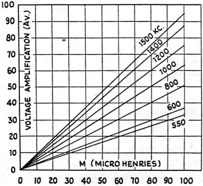
Fig. 3 - The maximum voltage amplification of a stage, plotted against the mutual inductance of an output transformer of good quality. The closer the coupling, the more unequal the gain.
Fig. 4 - The curves of amplification here correspond to those of Fig. 3; but are plotted against frequency, to show the greater efficiency at the low-wave end of the broadcast band.
Fig. 5 - A transformer designed to bring about more even gain throughout the range of broadcast frequencies. Lo-Co is tuned to about 500 kc., or 600 meters; L1 is smaller.
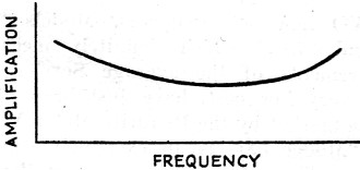
Fig. 6 - The characteristic curve of the transformer of Fig. 5, due to the decreasing reactance of Co as the frequency rises.
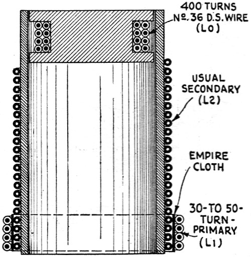
Fig. 7 - The completed radio-frequency transformer, designed to overcome the disparity in amplification at the ends of the band. Lo is to be shunted by a 40·mmf. capacity.
Fig. 8 - The slot-wound primary loading coil Lo of the circuit shown in Fig. 5, as applied to a standard R.F. transformer, The diameter of the coil is very small.
Fig. 9 - Curves obtained from a commercial antenna transformer: in (2), the primary is smaller and the coupling is looser. Note that the vertical scale is logarithmic.
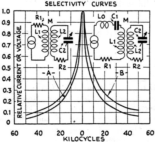
Fig. 10 - Selectivity curves at 1000 kc. of interstage coupler (A) and aerial coupler (B). The former has the high tube resistance R1, and the latter the high aerial capacity, in the primary circuit.
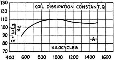
Fig. 11 - Above, effect of frequency on a coil; the "dissipation constant," inversely proportional to the resistance is the resultant of the effects shown below and of the frequency itself, which is a straight slope.
The determination of the tube voltages is more or less determined by the manufacturer's ratings; which often must be somewhat modified by considerations of power-pack load, cross-modulation effects, grid-circuit overload, etc. The selection of the system of volume control is apart from the design of the amplifier proper; that is to say, the system to be chosen is one which will have no effect on the tuning of the amplifier, but will exert its control over sufficient range to enable the operator to reduce the volume of the most powerful broadcaster to zero. Such matters are of course, quite intricate, but the analysis of each of the several problems can be made somewhat more or less independently of each other; and, after all, perhaps the most important problem of all is that of designing the radio-frequency transformers. We need hardly consider the tuning condensers at all. The design of these circuit elements is practically fixed. The economics of condenser design have practically fixed the number and size of the plates and the general arrangement of the frame structure; so that there is not much that can be done in this matter. Inductance Found by Experiment Consequently, the first part of the problem of radio-frequency transformer design is to calculate the inductance required to enable us to tune over the broadcast range with the particular condenser capacity we intend to use. Of course, knowing the required inductance value, only, is not sufficient; a coil must be constructed which will have this inductance. This can best be done by cut-and-try methods, backed up by a certain amount of experience along this line. In radio-frequency amplifiers designed around screen-grid tubes, which have very high plate resistances, the proportioning of the tuning inductance to cover the tuning range involves only the secondary of the coil. In other words, with the tuning condenser connected to the secondary, and with the coupling between the circuits quite loose because of the high plate resistance of the tubes, the tuning range is determined almost wholly by the secondary circuit, and independently of the primary. (Of course, the separate capacities of the primary and secondary coils, as well as their mutual capacity, have an influence on the tuning range; but this effect should be interpreted as a variation in the secondary inductance rather than as a coupling between the two circuits.) At any rate, let us suppose we have determined all these things; we have fixed the tube voltages, the tuning capacity and the secondary tuning inductance. We must now consider the design of the primary circuit of the R.F. transformer. Fig. 1 shows the simple circuit of a tuned R.F. amplifier using screen-grid tubes. The first thing we must determine about this circuit, in order to assist us in our work of transformer design, is how much voltage amplification per stage this amplifier can handle. We all know that, if we have too much gain per stage, the circuit will oscillate, because of the feed-back through the tubes, between the plates and grids. Of course, we are using screen-grid tubes, in which the grids are supposed to be screened from the plates; but it must not be forgotten that this screening is not 100 percent effective. Furthermore, there are other means of coupling between stages which are conducive to regeneration and oscillation; so we must be careful not to make the gain per stage too high. Limit of Amplification Fig. 2 shows the maximum gain per stage which can be used, assuming that the only source of feed-back is that which occurs within the tube between plate and grid. In other words, if this were the only coupling we had between stages, the gain shown in Fig. 2 is the maximum that could be used without having the circuits oscillate. If there is external coupling between the stages (as for example, in coupling resistors or condensers) the maximum amplification that can be used is less than that shown in Fig. 2; how much less, depends upon the amount and the kind of external coupling. At any rate, as we can see in Fig. 2, we cannot expect a gain per stage of much more than 80, in a three-stage amplifier using type '24 tubes. This may seem quite large; as a matter of fact it is large. It is extremely difficult to realize a gain per stage of even 70 or 80 over the broadcast range, except in an amplifier which is very well made, shielded, choked and bypassed with extreme care. This, of course, is out of the question in commercial radio receivers, on account of the cost involved. As a matter of fact, in well-designed commercial receivers, we can generally count on obtaining perhaps half the maximum possible gain; a limit due to the interstage couplings external to the tubes. The maximum possible gain is a function of the mutual conductance of the tube; that is, the greater the mutual conductance, the greater the possible gain. (See the article, "Mutual Conductance and Its Associates," March, 1931, Radio-Craft. - Editor.) On the other hand, the greater the number of stages, the lower the maximum possible amplification. The same is true of the grid-plate capacity of the tube; to double it reduces the amplification thirty per cent. We must now consider how much gain per stage we actually obtain in a typical circuit. Of course, the actual gain depends on the mutual conductance of the tube, the resistance of the tuned circuit (or the coil's "dissipation constant" Q), and the coupling between the primary and secondary (M). The Rp of the tube also has an effect on the gain, but this effect is quite small in screen-grid tube circuits. Mutual Inductance of the Coil In Fig. 3 we have curves which show the relation between the mutual inductance of the transformer and the voltage amplification obtained at different frequencies. The value of the coil's dissipation constant Q (which is 6.28 x f x L/R2) is here assumed to be 100; which is a fair value for commercially-designed coils of good quality. On the basis, it can be seen from Fig. 3 that; at 1000 kc., we can expect an amplification of about 32 per stage if the mutual inductance is 50 microhenries. The curves show that, as we increase the mutual inductance, the gain goes up steadily. This means that, if we double the primary turns, we will double the gain; because the mutual inductance varies as the primary turns. Another thing, which Fig. 3 teaches us, is that the voltage amplification increases as we increase the frequency. This can, perhaps, be seen more clearly by plotting the curves in a different manner, as in Fig. 4; here the voltage amplification is shown plotted against the frequency, for various values of mutual inductance. For example, if the mutual inductance is 50 microhenries, we can expect a gain of 32 per stage at 1000 kc. as before. However, if we keep the mutual inductance constant and increase the frequency, (tune to a lower wavelength), we see that the gain rises steadily. This is the frequency-characteristic which we obtain in all radio-frequency amplifiers employing the simple two-coil R.F. transformer. At high frequencies the gain is great, and at low frequencies it is small; and, the greater the mutual inductance, the steeper the curve. Problems of Multi-Stage Design It must be remembered that the curves shown here are for a single stage. With two stages, alike in design, the total amplification at any frequency is the square of the amplification of one stage; if there are three stages, the total amplification is the cube of that of one stage. This means that, if we plotted the curves of Fig. 4 for three stages instead of one, we should find the curves very much steeper; and the difficulty which designers find in R.F. amplifiers would be more obvious. In a three-stage amplifier, the R.F. amplification at 1500 kilocycles may be as high as three to five times that obtained at 550 kilocycles; or even more, depending upon the particular design. It is on this account that attempts have been made to design R.F. transformers which will give reduced amplification at the higher frequencies, and greater amplification at the lower frequencies. It is necessary, at the outset of such a design, to provide for keeping the coupling sufficiently loose; so that the reaction of the primary circuit will not appreciably affect the secondary tuning. This is a very necessary requirement, in order to make it possible to tune the amplifier over the entire broadcast range, while avoiding resonance effects, due to the primary, which would make the tuning of the secondary uncertain at certain frequencies; such sometimes occur in the tuned circuit coupled to the antenna, when very large antenna capacities are used, or when the antenna coupling is very tight. This being the condition - that the coupling between the primary and secondary must be loose - it is clear that the way in which the amplification varies with frequency will depend mainly upon the design of the primary circuit. Returning to Fig. 3, it will be obvious that the amplification is dependent upon the mutual inductance between the primary and secondary. Hence, if .we can make this mutual inductance vary in any way which we desire, we may likewise be able to control the amplification accordingly. A Compensatory Coil Design This is what is done in actual practice; in one design, illustrated in Fig. 5, a local tuned circuit in the primary, consisting of a loading inductance Lo shunted by a condenser Co, is placed in series with the regular primary L1. The secondary L2B is of the usual design. The self-inductance Lo is quite large compared with the inductance L1; so that at low frequencies (as at 550 kc.) L1 has little effect in comparison. Lo and Co are so proportioned that this local circuit is resonant at about 500 kilocycles, just above the upper wavelength of the tuning range of the amplifier. The mutual inductance Mo (between the coil Lo and the secondary L2) is opposed to the mutual inductance M, between the primary L1 and the secondary L2. In other words, Lo and L1 are arranged to "buck" each other. Now let us see what happens: Suppose we tune to a long wave , L1 has little effect because it is a small inductance; the signal current in the local tuned circuit LoCo is quite large, because we are near the resonance frequency of the local circuit. The signal energy is then transferred to the secondary via the mutual inductance Mo, which can be so adjusted that the amplification is quite large. Now, suppose we gradually tune to higher and higher frequencies. As the frequency increases, it departs further and further from the resonant frequency of LoCo, and Lo becomes a choke coil in effect. Co acts as a by-pass condenser more and more, as the frequency increases; so that the high impedance of Lo does not obstruct the signal to any considerable amount. Now the regular primary L1 begins to work, transferring power to the secondary via the mutual inductance M. At very high frequencies, the system acts as if Lo and Co were not present; since Co becomes an effective by-pass. So this is an arrangement which will provide great amplification at low frequencies, because of the resonance effects in the primary, and, likewise, high amplification because of the usual laws pertaining to the simple primary circuit L1. By combining these effects we obtain a curve like that shown in Fig. 6 - high at both ends and drooping slightly near the middle. By properly proportioning the various windings, the drop in the middle of the curve can be made small; and the curve will be as nearly linear as can be practically desired. There are various arrangements of this system, but all work on the same principles. Sometimes the condenser Co is omitted, and the winding Lo is so made that its self-capacity (or distributed capacity) is sufficient to cause the resonance and by-passing effects. The coil Lo may also be located at various points of the secondary, in different designs. There is no rule which can be given. The whole effect is so complicated that the only way in which to design such a system is to do it experimentally; that is, use the cut-and-try method. Constructing the Transformer Figs. 7 and 8 show the construction of such an R.F. transformer. The primary loading inductance Lo is a random-wound coil of 400 turns of No. 36 D.S.C. wire on a small bobbin, in a slot 3/16-inch wide, and having an inside diameter of 1/2-inch. The construction of this bobbin is shown in Fig. 8. The bobbin is inserted into the top end of the tubing on which the secondary is wound; the latter winding starting just below the bobbin. At the lower end of the secondary - away from the grid end - is wound the normal primary L1, upon a laver of empire cloth; this part of the construction is quite usual. The coil Lo is shunted by a fixed condenser of 40 micromicrofarads (40-mmf.) value. Before closing the discussion, we must include a few words on the antenna coupling, and see how much voltage step-up we can expect in this tuned circuit. The constants which have been assumed, in making the calculations for the preceding curves, are those shown in the curves of Fig. 9; which are experimental values taken on a regular commercial R.F. transformer. In making the calculations for the antenna circuit the constants shown on the curve were assumed. Two curves are shown; one of these is for a fairly large coupling and a fairly large antenna; the second is for a smaller antenna and looser coupling. In the lower curve these values have been reduced, in order to see how much the amplification is lowered. As these curves show, we can expect the voltage amplification in the antenna coupling transformer to vary from perhaps unity to as much as 30. This effect also contributes considerably toward making the amplification characteristic of the entire amplifier quite steep with regard to frequency; and it must be compensated for by the special transformer primaries. Selectivity Found in Number of Circuits Before closing it will be well to include a few remarks about the selectivity to be expected from such circuits. Fig. 10 shows curves which have been calculated for the two circuits - the interstage circuit and the antenna circuit. It will be seen that there is not a great difference between the selectivities of the two circuits, although the antenna circuit is somewhat less sharp in tuning than the interstage circuit; which we may well expect, considering the resistance of the antenna. In the interstage coupling the primary resistance (the plate resistance of the tube) is so great that the primary has little effect on the tuning of the secondary and on its selectivity. Although these curves may seem to be quite broad, upon first inspection, it must be remembered that the great selectivity of an amplifier is dependent mainly upon the number of tuned circuits, and not upon the selectivity of each single circuit. By this we mean that only small improvements in over-all selectivity can be made by improving the selectivity of the individual stage; practical, commercial tuned circuits are about as selective as we can make them without adding considerably to the cost. Great improvement in selectivity may be obtained by adding a special tuned circuit to the amplifier; whereas, a slight improvement in the selectivities of the several tuned circuits (as by reducing their losses), will hardly result in any improvement that might be considered appreciable.
Posted December 22, 2016 |
|