|
April 1938
Radio-Craft
 [Table of Contents] [Table of Contents]
Wax nostalgic about and learn from the history of early electronics.
See articles from Radio-Craft,
published 1929 - 1953. All copyrights are hereby acknowledged.
|
This story from the April 1938
issue of Radio-Craft magazine reports on a ground-breaking (at the time)
new television system, written by none other than the inventor himself - Allen B.
Du Mont. Television in the era was still largely in the experimental phase
with various schemes for transmitting, receiving, and displaying still vying for
dominance as the national / international standard. The now-familiar
NTSC (National Television
Standards Committee) standard, which ultimately passed over the Du Mont system,
was adopted in 1941. Most communications historians are of the opinion that the
"Phasemejector" developed by Du Mont was unquestionably superior from a technical
and practical perspective for an end-end television system based on relatively low
manufacturing costs, high reliability of fielded systems, and ease use. Politics,
it is said, is responsible for the inferior standard adopted in its stead - the
aforementioned NTSC. Your time taken to read the article is time well spent if you
appreciate irony.
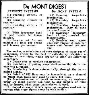
The Du Mont Television System
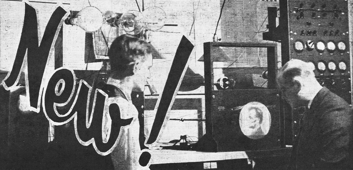
Fig. A - New Du Mont television apparatus being tested in
the laboratory. No sweep, frame, or blocking frequencies need to be generated at
the receiver.
Television Takes a Big Step Forward! Ingenious new circuit arrangement makes
reception - of various numbers of lines per frame and frames per second - possible
with simplified television receiving set. A "Phasmajector" demonstrates principles
involved.
Allen B. Du Mont
Television systems now being used commercially in Europe and experimentally in
this country are basically the same. A photoelectric mosaic tube, scanned by a cathode-ray
beam, is used for picking up the images at the transmitter; a cathode-ray tube with
a fluorescent screen for reproducing the picture is used at the receiver. Sweep
circuits are employed at the transmitter to scan the picture. The video signals
from the pick-up tube are transmitted by the video transmitter, as well as complicated
synchronizing and blanking pulses. At the receiver the video signal is used to modulate
the cathode-ray beam, the synchronizing pulses are used to hold the picture steady
and the blanking pulses eliminate the undesired portion of the sweep trace.
Present Systems vs. Du Mont System
The present systems have a number of disadvantages which, in some measure, have
held back their use on as large a scale as sound broadcasting. For one thing the
receivers are costly because of the necessity of providing local sweep circuits
and separators. Second, a very wide frequency band is necessary for transmission,
and, third, receivers can only receive pictures having a given number of lines per
picture and pictures per second. There are numerous other disadvantages among which
are fussy adjustments at the receiver ,and the necessity of using ultra-shortwaves
for transmission which limit the distance the pictures can be sent.
The Du Mont Television System, on which patents are pending, eliminates all these
disadvantages and for the first time provides a practical, simple, low-cost television
system of high definition. The basic difference between this and the present systems
is that, instead of having local sweep oscillators at the transmitter and receiver,
the sweep voltages themselves are transmitted. This in itself seems a simple change
- and it is, but a large number of details had to be worked out in order to accomplish
this. Considerable work toward this end has been carried out for the past several
years at our laboratory, and well over a year ago permission to transmit using this
system was requested from the F.C.C., but to date, due to the usual red tape, no
decision has been made on the application. Regardless of this, our tests in the
laboratory conclusively prove the advantages gained by this system, which are obvious
to technicians when the following facts are considered.
Referring to the various disadvantages of the present system we note that the
receivers are costly because in addition to having the usual radio receiver, local
sweep circuits with their complicated separator circuits must be provided. With
the Du Mont System, the receiver needs no local sweep circuits and is practically
the same as the present-day sound receiver, except that it has the higher frequency
response necessary for high-definition pictures. Furthermore; no provision has to
be made for interlacing which, together with .synchronizing, causes considerable
trouble in the present system. To sum up, the Du Mont receiver is practically the
same as a modern sound receiver, no local sweeps, synchronizing or interlacing controls
or circuits being necessary.
 World-Wide Television Now Practicable! World-Wide Television Now Practicable!
Taking up the point that a very wide frequency band is now necessary, the fact
that in the Du Mont System a higher interlace ratio can be employed permits much
higher definition pictures with the same frequency band, or allows the same definition
picture to be transmitted on a much narrower frequency band. The reason for this
is that, because of the difficulty of synchronizing and interlacing with the present
system, it is impossible to use a higher ratio than 2.
In the Du Mont System, because it cannot possibly be out of ,synchronization,
there is no limit to the interlace ratio; hence the saving in both the radio spectrum
and the receiver is considerable. With present, systems a 6 megacycle band is necessary
for 441 lines, 60 fields per second and an interlace ratio of 2.
Our tests have shown that, with the same number of lines and frames per second,
we can use an interlace ratio of 4, requiring a frequency band of only 3.0 megacycles.
This means that two transmitters can be used where only one can now be used.
Furthermore, a longer wave band can be used, allowing world-wide transmission.
Taking this :from another angle, if we decide to use the full 6 megacycle band we
can transmit pictures of 882 lines, which is comparable to the finest motion pictures
now available. In addition the receiver will have only the same frequency requirements
as at present.
A Question of Economics - Answered
The third point to be discussed i.e., that with the present system receivers
can only receive pictures having a given number of lines, per picture and pictures
per second, is important because the greatest reason for holding back commercial
television, in the opinion of the writer, has been this consideration. No company
will assume the responsibility of bringing out sets with a certain definition (number
of lines) and have them become obsolete in a year or so because of advances in the
art. Yet, with the present system, this holds true. Changes have been made in the
past seven years, raising the number of lines from 48 to 60 to 120 to 1]80 to 240
to 343 and now to 441. The present detail is fairly good, but nowhere near the ultimate,
and it is certainly not desirable to make sets useless when further changes occur
or to decide now on a standard which later on, would be undesirable. With the Du
Mont receiver a picture of any number of lines can be received, up to 882, providing
the receiver has amplifiers at least as good as those necessary for present 441-line
transmission. A person buying a receiver using this principle can see pictures from
transmitters using various numbers of lines and, when the transmitters increase
the detail (number of lines), his receiver does not become obsolete.
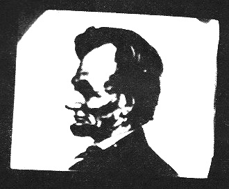
Fig. B. An unretouched photograph of the screen on the receiving
tube.
In this new system the video transmitter does not have any synchronizing or blanking
pulses inserted in the video signal, so the full power is available for picture
signals (instead of only 80% with the present system, due to 20% of the power being
necessary to transmit the synchronizing and blanking pulses).
The line and frame sweep voltages have been transmitted with satisfactory results
by several different methods. In one method these voltages are transmitted over
the audio carrier. The line frequency is above the audio range and a simple filter
keeps this frequency out of the loudspeaker. The frame frequency is also transmitted
and means are provided so that it does not interfere with the audio system. Satisfactory
results can be obtained by transmitting the sawtooth sweep pulse itself or transmitting
sine waves of the same frequency and converting them to sawtooth waves at the receiver
by means of a simple rectifier-filter arrangement. When the receivers are to be
used on the same power system as the transmitter, it is not necessary to send the
frame sweep at all, as a rectifier-filter circuit at the receiver supplies the necessary
frame deflection. This condition exists in well over 90% of the country, further
simplifying the receiver problem in most sections.
It is believed that the Du Mont System of television is a marked improvement
over present systems and eliminates the major difficulties which have been retarding
the use of television receivers by the average citizen.
Laboratory workers who specialize in television research find it too inconvenient
and time-consuming to attempt to design and test equipment where the image-subject
is continually changing in position, lighting, etc., as would be the case if live
subjects are used. Hence the development of the following interesting television-transmission
device which serves the dual purpose of facilitating general television test work
and of demonstrating the capabilities of the new television system.
The "Phasmajector" - New Television Term (and Device)
The demonstrator, experimenter, designer and tester are now entirely independent
of the temperamental television transmitters heretofore depended upon for video
signals. Instead of waiting for days and even weeks to tune-in on the elusive television
images, let alone figuring out the. veritable cross-word puzzles of signals of unknown
scanning techniques, the television worker now has his own signals constantly on
tap and of known technique. And this is of incalculable value in accelerating further
television progress.
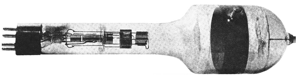
A radically new development by the writer and· his associates, the "Phasmajector"
(Greek for Image Emitter) - a modified form of cathode-ray tube - provides a uniform
television test signal with relatively inexpensive associated apparatus. In place
of the usual fluorescent screen swept by the cathode-ray beam and glowing to weave
an image, there is in the Phasmajector (see Fig; C) a metallic plate on which is
printed the desired picture or test pattern. Also, the tube includes a collector
electrode as well as the conventional cathode-ray tube gun and deflecting electrodes.

Fig. C. The "Phasmajector", heart of the Du Mont System,
which simplifies television reception, yet makes more detail easily possible.
When used with proper sweep circuits and amplifiers, the picture printed on the
metallic plate can be readily scanned and transmitted to a receiver for reproduction
on a standard television viewing tube. It is also possible to use the standard oscilloscope
cathode-ray tubes for viewing, as demonstrated by the photographic reproduction,
Fig. B, of the image received on a Du Mont type 34-XH or 3-inch oscilloscope
tube.
The new image-transmitting tube or Phasmajector operates on the principle of
varying secondary emission from the image plate. In other words, as the cathode-ray
beam scans the image on the metallic plate, varying amounts of secondary electrons
are released depending upon whether the beam impinges upon metal or special ink
used to print the picture. A larger number of electrons are released when the ray
strikes the metal than when it strikes the ink. The varying voltage output is picked
up by the collector electrode and fed to the grid of the video amplifier. This signal
is very stable and of much better quality than can be obtained from a photoelectric
mosaic pick-up tube because of the absence of capacity effects. The amplitude of
the signal may be as high as 10 volts with high-impedance coupling and can modulate
a television viewing tube directly without any video amplifier. The signal is 0.2-volt
across a 10,000-ohm load.
For a simple television demonstration, two standard oscilloscopes such as are
used by radio Service Men, can be employed very conveniently. One of the two oscilloscopes
is equipped with a Phasmajector tube in place of the usual cathode-ray tube, and
the other is utilized with its usual tube. Certain slight modifications are required,
but the oscilloscopes can still be used for their normal purposes when desired.
With such a simple, inexpensive arrangement all the principles of a complete television
system can be readily demonstrated. Either horizontal or vertical scanning of any
desired number of lines and any interlacing arrangement can be used.
The Phasmajector Type 1 has the same operating voltages as the Du Mont 34-XH
3-inch cathode-ray tube. It has two additional electrodes, however, namely the collector
electrode and the image plate. The collector is operated several hundred volts positive
with respect to the anode, and feeds into the grid of the amplifier tube.
The image plate is normally grounded to the anode.
The present Phasmajector available to demonstrators, experimenters and others
has on its plate an excellent line drawing of Abraham Lincoln. In demonstrations
recently staged at the the writer's laboratories, the drawing was first scanned
with a half-dozen lines or less, yet the coarse image reproduced could be at least
identified. Especially so by increasing the interlacing ratio. Stepping up the scanning
pattern to about 100 lines and adjusting the intensity and focusing controls, an
excellent image was obtained. The individual luminous lines were observed to disappear
as they overlapped and blended together. Interesting distortion could be produced
at will, such as by horizontal expansion of the image, whereupon Mr. Lincoln developed
an overgrown proboscis and an Ethiopian hair cut. Vertical expansion likewise produces
a humorous effect, this time by way of a more than intellectual forehead and a decidedly
sour expression, let alone a crop of hair that would bring joy to any hair tonic
manufacturer.
Posted August 16, 2023
(updated from original post on 4/1/2017)
|