|
December 1942 Radio-Craft
 [Table
of Contents] [Table
of Contents]
Wax nostalgic about and learn from the history of early electronics.
See articles from Radio-Craft,
published 1929 - 1953. All copyrights are hereby acknowledged.
|
When civil engineers and
mechanical engineers take their introductory classes in hydraulics, are they
taught that the functional equivalent of water pressure in a pipe is equivalent
to voltage in a battery, and that the rate of water flow is equivalent to current
in a circuit, and that the diameter and surface finish of pipes are equivalent
to resistance in electricity... in the same manner that electronics students
are taught from the opposite point of view? The answer is 'yes,' they are. It's
kind of funny how for some reason using an analogy from another familiar physical
process always seems to help make more sense of the subject at hand. In fact,
for macro level problems, the mathematical equations that govern mechanical
and electrical systems are identical, with only the objects and units being
different. Oscillating LC (inductor and capacitor) tank and damping circuits
have equations that look just like spring and dashpot systems that perform analogous
mechanical functions - both in the time domain and the frequency domain. It
is not until you get into really specific components and functions that unique
equations emerge for electrical and mechanical studies. This article that appeared
in a 1942 edition of Radio-Craft illustrates how the basics have not
changed in over half a century.
Electrical Quantities
By Willard Moody*
|
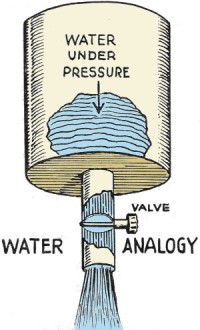
Fig. 1 - Voltage / water pressure analogy.
|
Most of our readers are already familiar with the helpful and instructive
explanations of electrical theory which Mr. Moody has given us from time to
time. In these days when thousands of school boys and young men are studying
radio before entering the armed forces, they must cram in a month or two what
usually takes a year to learn. So to these young men we say that Mr. Moody's
articles will be found of tremendous interest and assistance. .
Th volt is the unit of electromotive force or potential difference, which
will send a current of 1 ampere through a resistance of 1 ohm. A standard battery
in the Bureau of Standards has a terminal voltage or potential difference of
1 volt, when constructed according to certain specifications. In radio work,
sensitivity of a receiver may be stated in microvolts. A microvolt is a volt
divided by the number 1,000,000, or 10 raised to the minus six power. Sensitivity
is also stated, occasionally, in millivolts per meter. A millivolt is a volt
divided by 1,000.
Voltage may conveniently be considered as pressure. The idea of a water tower
filled with water and exerting pressure upon the surface of a pipe connecting
to the tower is a simple analogy or explanation, Fig. 1.
A storage battery or dry cell may be considered a reservoir of electrical
energy from which current is drawn when the pipe connecting to the battery is
not plugged up. If a plug in the form of resistance is inserted in the pipe,
there will be opposition to the flow of current and only a thin stream will
leak through. Electrical leakage is very similar. The positive terminal of the
battery of electrical generator may be thought of as the point where the pipe
connects to the tank and the pressure exerted on the pipe at this point will
be the potential force or voltage.
Current
The current in an electric circuit is rated in amperes or fractional parts
of the ampere. In radio work a meter may have a movement, or full scale reading
of 1 milliampere.
A milliampere is an ampere, divided by 1,000, or expressed decimally is 0.001
ampere. An ampere is the current that flows in a circuit having a resistance
of 1 ohm and a voltage or potential difference of 1 volt.
In certain instruments, the sensitivity or full scale reading may be 50 micro-amperes.
A micro-ampere is an ampere divided by 1,000,000.
Current may be thought of as a flow of electrons through a wire similar to
a flow of water in a pipe. A heavy current (or large number of amperes) is like
a flow of several gallons of water per second. A light current would have a
small number of amperes. In radio, a small current would be measured in micro-amperes.
An ordinary house fuse has a rating of ten or fifteen amperes in the branch
circuit, and may be 25 amperes in the wattmeter circuit. A radio of average
console size might draw 1-1/2 amperes from the 115 volt power line. A 150 watt
bulb would draw about the same current in amperes on the same line.
Resistance
Resistance is stated in ohms. An ohm is the unit of opposition offered to
the flow of electric current, and in the Bureau of Standards is the resistance
of a piece of special wire under certain conditions of temperature. One ohm
will be equal to 1 volt divided by 1 ampere. That is Ohm's Law and was discovered
by a scientist named Simon Ohm in whose honor the unit is named. Ohm's Law is
so fundamental and is used so often in radio and electrical work that it must
be thoroughly understood.
Ohm's Law states that current flowing in a circuit is equal to the voltage
across the circuit, divided by the resistance of the circuit, or expressed in
symbols:
I = E / R
This relation holds true only when I is in amperes, E is in volts, and R
is in ohms. If a current was measured in milliamperes (or thousandths of an
ampere), it would have to be changed to amperes by being expressed as a decimal
part of an ampere, before being used in the Ohm's Law formula.
Suppose R were in megohms (mega, million, plus ohms). It would not have to
be changed to be used in the formula, because it is already in ohms.
Power
|
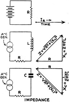
Fig. 2 - Impedance triangles
|
The electrical power in a circuit is rated in watts. One horsepower is equivalent
to 746 watts. In amateur radio transmitters the plate power to the final stage
is legally limited to 1,000 watts or 1 kilowatt. A large broadcasting station,
on the other hand, may have a power of 50,000 watts or 50 kw.
An ordinary console radio may have a power rating of 150 watts: but the circuit
resistors used in that radio are rated 1 watt or 1/2 watt. An electric soldering
iron might have a rating of 100 watts; and an electric clock might draw no more
than 1/2 watt.
The watt in a direct current circuit is equal to the product of voltage and
current, or expressed as a formula:
W = I x E
The watt is the unit of electrical energy or work, hence the symbol "W."
Lately, however, the symbol "P" has enjoyed wide usage and also represents wattage
or power. The capacity of a water tank represents the electrical power in a
water analogy. The wattage dissipation of a resistance will be the power lost
as the result of heating the resistance, which is work done. An electric lamp,
when heated, radiates both heat and light. That is, the conversion of electrical
power into other useful form of energy. A radio loudspeaker will convert electrical
power into mechanical power, and this in turn will set up a pressure in the
air which reacts on our ear drums. The pressure on the ear drum is then converted
into an electrical current in the nerve and transmitted to the brain, where
we receive consciousness of the sound heard.
An electric motor, when fed electrical power, turns its shaft and does work.
Conversely, an automobile generator has its shaft turned by engine, and is thus
supplied mechanical power, which it converts or changes into electrical power
that is used to charge up the storage battery in the car's ignition system.
Power Factor
The power is an alternating current circuit will be equal to the product
of three factors, that is, voltage, current, and a third factor called the "power
factor."
The power factor of a circuit is the percentage of resistance in the circuit.
A lamp bulb, being all resistance practically, has unity power factor; this
is expressed as 1. The voltage times the current times 1 will be the power.
If the power factor is something less than 1, it will be expressed as a percentage,
say 90%, which is shown as .9 and is used to multiply the voltage and current.
An ordinary A.C. voltmeter or ammeter, such as used in radio servicing or
electrical power work, will read in what are termed effective values. The effective
value of an alternating current produces the same heat in a one-ohm resistance,
as the heat that is produced by a direct current. If the direct current voltage
were 1 volt and the resistance were 1 ohm, the current would be 1 ampere. If
an effective alternating current volt were supplied to a resistance of 1 ohm,
the effective current would be 1 ampere and the heat produced in the 1 ohm resistance
would be the same as with the direct current. The power would also be the same
and the power factor would be 1, or unity.
|
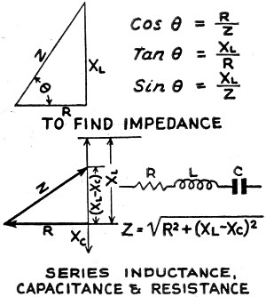
Fig. 3 - Series inductance, capacitance & resistance
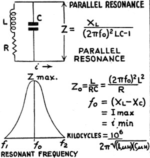
Fig. 4 - Resonant frequency
|
The power factor in an alternating current circuit takes into account a quantity
called impedance. The symbol "Z" is used to represent impedance and this quantity
is stated in ohms. The ratio of R to Z is called the power factor. That is,
R divided by Z equals the power factor. In a parallel circuit of inductance
and capacity, at resonance, the impedance is minimum and is a pure resistance.
This is so because the reactances of the circuit have cancelled out and only
the resistance of the coil is left. All these new terms will be explained fully
as we go on, Fig. 3.
The power factor is also equal to the cosine of the phase angle, or, cos
θ (theta) equals R divided by Z.
Phase Angle and Reactance
In a direct-current circuit, when the battery is connected to a resistance,
the current immediately climbs to its peak or maximum value and remains there
so long as the battery is connected. The action is instantaneous or occurs at
once, Fig. 5.
In an alternating-current circuit, when voltage is applied to a coil, the
current does not immediately flow into the coil because there is a magnetic
field about the turns of wire in that coil, which creates a back electromotive-force
that is opposite in direction to the applied electromotive force or voltage.
As a result, there is a time-lag between current and voltage, and the voltage
in a coil circuit leads the current by 90 degrees. This effect is called reactance
and is measured in ohms, just as impedance and resistance are measured in ohms.
The inductive reactance limits the current flow in an alternating current circuit.
The current I will be equal to E divided by X. The symbol for reactance is X,
Fig. 2.
It is obvious that the effect of the inductance of the coil, is to limit
the current. This limiting will increase as the frequency of the alternating
current is increased. The equation for inductive resistance is:
XL = 2πfL
where "L" is the inductance in henrys, "f" is frequency in cycles and "XL"
is the in-ductive reactance in ohms.
Capacitance and Reactance
As the reactance of the coil increases with frequency or an increase in the
inductance, the reactance is said to be a positive quantity.
A condenser or capacitor, on the other hand, has a negative characteristic,
Its reactance varies inversely or negatively as the capacity or frequency is
raised. The equation for capacity reactance is:

where "XC" is in ohms, "C" in farads, "f" in cycles.
When voltage is applied to a condenser, current flows into the plates of
the condenser. But before there can be a potential difference between the condenser
plates, or before those plates can acquire or get a charge of electricity, current
must flow into the plates. Thus, the current gets there first and the current
is said to lead the voltage by 90 electrical degrees. The voltage is said to
lag the current (which is just the opposite of what holds true in the case of
the coil).
|
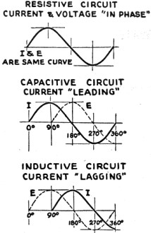
Fig. 5 - Resistive circuit current & voltage "in
phase"
|
In a direct current circuit voltage and current reach their peaks (or maximum
values) at the same instant.
In an alternating-current circuit the voltage and current reach their peak
values at the same instant only when the circuit is composed of pure resistance
and has no reactance. Under that condition the power factor, or ratio R/Z, is
said to be unity, and the circuit is termed "resistive." If the power factor
is less than 1, the circuit is partially "reactive."
An example of such a condition occurs in parallel resonant circuits (that
is, tuning circuits), where, when the condenser (or the inductance in some cases)
is tuned, the reactance of the condenser equals the reactance of the inductance.
Being equal there is no effect on the phase relationship, so the resistance
limiting current flow consists of the resistance of the wire in the inductance
and in the leads. This resistance has no effect on the phase angle. The so-called
peak of the resonant frequency is attained under these conditions. (See Fig. 4.)
The diagram shown, consisting of L, R and C is the equivalent circuit of
the inductance, with its d.c.-resistance R; and the condenser C. Land C of course
are in terms of ohms to make this equivalent circuit uniform.
The formulae given show the relationships existing; and the resonant frequency
diagram shows peak or resonant frequency between two side-band frequencies f-1,
and f-2.
Summary
It is important to remember that power is never lost in a pure reactance.
Power is lost only in resistance. Reactance stores energy, and it is the reactance
of a coil or condenser that makes the coil or condenser act as an electrical
storage tank. In a parallel circuit, at resonance, when coil reactance equals
condenser reactance, there is a cycle of energy being poured from coil to condenser
and vice versa. It's like having two glasses, one filled with water and the
other empty. You take the water in one glass and pour it into the other, then
back again. You can repeat this indefinitely. If you spill some of the water,
that is power lost. Your clumsiness represents resistance. If you are very clumsy,
you are very resistive and lose power readily. A coil having a high resistance
would lose power constantly in the circuit, until all of the available power
was used up. The same applies to a condenser. In any case, the more efficient
is the coil or condenser, the less is the power factor. The energy being poured
back and forth represents reactive or circulating current. It is phantom or
unreal power although the current is there and is very real. The wires or conductors
in an alternating current system, such as the wiring in a factory, must carry
reactive current if the power factor of the line is not close to 100%. Synchronous
motors are sometimes switched into such circuits, because they draw a reactive
current which balances the system and restores the power factor.
*Radio Instructor
Posted February 22, 2021
(updated from original post on 9/21/2014)
|