|
March 1948 Radio-Craft
 [Table
of Contents] [Table
of Contents]
Wax nostalgic about and learn from the history of early electronics.
See articles from Radio-Craft,
published 1929 - 1953. All copyrights are hereby acknowledged.
|
Every time I see one of these articles
on "modern" medial electronics it makes me think of the Star Trek IV movie
titled, "The Voyage Home," wherein
Dr. McCoy (aka "Bones") intervenes as a 20th century brain surgeon is about to operate
on Chekov - "My God man, drilling holes in his head is not the answer!" The 1948-vintage
electrocardiograph featured in this Radio-Craft magazine article looks
like it was built from parts salvaged from World War II field gear. Having
a doctor attach wires to you is scary enough, but back when the probes were powered
by instruments using circuits with 200-300 volts of plate bias in them would
add an extra level of anxiety.
BTW, have you ever wondered how "star dates" in Star
Trek were determined? As it turns out, the system has not been consistent throughout
the series from television and the movies then back to television. It began as a
random number to avoid needing to specify a particular century and ended with a
system that included which season the TV season was. Now you know.
Electronics in Medicine - The Electronic Cardiograph
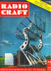
How the cardiograph is used. Third electrode is over the heart.
Part I - The electronic cardiograph, its fundamental theory and notes on application
methods
By Eugene Thompson
Courtesy Sanborn Co., Cambridge, Mass.
Medical electronics embraces all these electronic devices and techniques which
are employed in the diagnosis and treatment of disease. Among these techniques are
electrocardiography, bleed pressure and pulse recording, photoelectric plethysmography,
and photoelectric colorimetry. Electrocardiography equipment serves as a basic component
for a number of the techniques.
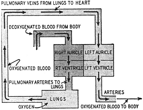
Fig. 1 is a diagrammatic sketch of the heart and the flow of bleed through
it. It is essentially a four-chambered mechanical force pump. Its function is to
pump deoxygenated blood, which is returned to it from the body via the veins, through
the lungs, where it picks up a fresh supply of oxygen, and thence back to the body
by way of bleed vessels known as arteries. The chambers of the healthy heart contract
in a definite, orderly, and rhythmic sequence known as the cardiac cycle.
The Blood Circuit
Referring to. Figure 1, the cycle starts as a quantity of deoxygenated bleed
empties into the right auricle. At this time this chamber is in its resting phase,
or diastole, which lasts for 0.7 second. At the end of this filling period the right
auricle contracts (systole), which lasts 0.1 second and forces the blood into the
right ventricle. After doing this the auricle returns to its diastolic phase (0.7
second) to collect some mere deoxygenated bleed. Immediately after it receives the
bleed from the right auricle, the right ventricle which has been in diastole for
the past 0.5 second, undergoes systole. Ventricular systole lasts for 0.3 second
and propels the deoxygenated blood through the lungs, where it becomes oxygenated,
and back to the left auricle. This chamber in turn squeezes the blood into the left
ventricle from whence it is pumped back to the body again.
The time relationships for diastole and systole of the left auricle and ventricle
are the same as these given for the right auricle and ventricle. The halves of the
heart work together.
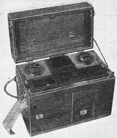
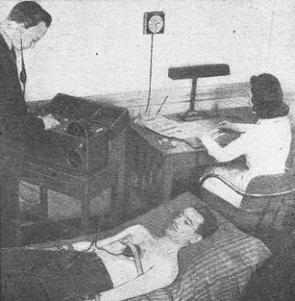
A direct-writing type of electrocardiograph.

Fig. 1 - Heart, in radio-style block diagram.
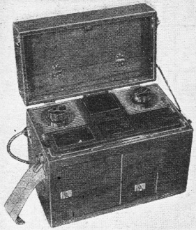
Fig. 2 - Hookup of early equipment with Einthoven string
galvanometer.

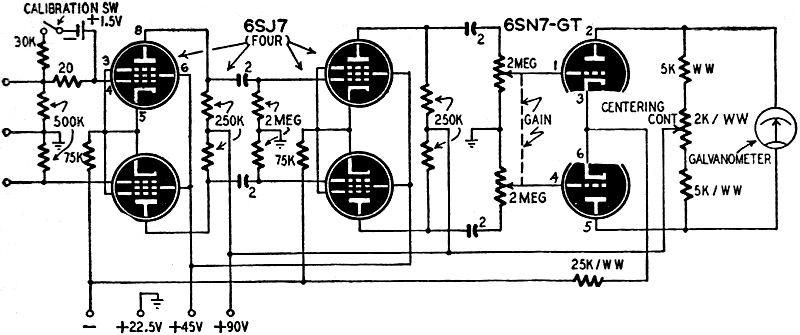
Fig. 3 - Audio amplifier designed for the electrocardiograph's
very low-frequency output.

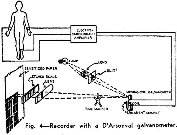
Fig. 4 - Recorder with a D'Arsonval galvanometer.
The two auricles contract simultaneously, and then the two ventricles do the
same. Each of course is ejecting a different type of blood.
By far the most striking thing about the cardiac cycle is its rhythmicity. We
now knew that the contractions of the heart are timed and controlled by nerve impulses
which arise within the heart itself. It has been demonstrated by cathode ray oscillography
that nerve impulses are electrical in nature. Consequently, as these impulses stream
through the heart they leave the tissue through which they pass momentarily electronegative
with respect to the rest of the heart and body. The resultant shifting of this electronegative
area with the passage of the nerve impulse constitutes a minute electrical current
which can be detected with the aid of sufficiently sensitive recording apparatus.
Early Instruments
The first practical electrocardiographic recorder was the Einthoven string galvanometer.
The basic arrangement of this device is shown in Fig. 2. Although this type
of recorder is still widely used, the modern trend is away from this design and
toward the more versatile electronic recording system.
Fig. 3 is a schematic diagram of a typical electrocardiograph amplifier.
Although all such amplifiers are not of push-pull design, this type is capable of
doing everything that non-push-pull amplifiers can do, and has several additional
advantages. Among the more important of these are: push-pull can handle signals
of greater amplitude than single-channel amplifiers under the same operating conditions;
the power output is greater; extraneous noises, such as those produced by x-ray
or diathermy apparatus, feed into the amplifier 180 degrees out of phase and hence
are bucked out to a large extent; second and all even-number harmonic distortion
is reduced.
Because the amplitude of the action potentials produced by the heart are 1 millivolt
or less under normal conditions, an electrocardiograph amplifier must have high
gain. In the unit shown in Fig. 3 this is accomplished by the 2 stages of push-pull
amplification. Employment of pentodes rather than triodes results in a much higher
over-all gain per stage. Furthermore, using the 6SJ7 is an excellent pentode in
that it is possible to obtain a gain in the neighborhood of 80 to. 100 with relatively
low operating voltages (plate supply voltage 90 volts).
Another important characteristic of the heart's action potentials is their low
frequency. This imposes the necessity for a long time constant in the amplifier
and accounts for the higher than usual values of the interstage coupling condensers
and grid lead resisters.
One further complication is added because of the amplifier's low pass characteristics.
An a.c. power supply cannot be used, because of two reasons. First, the a.c. on
the filaments would appear on the record. Second, the d.c. plate and screen voltage
would produce the same effect, unless the power supply were of such exceptional
design that the ripple content would be of very negligible proportions. These difficulties
are easily solved by using batteries for the filament supply, grid bias, and the
plate and screen voltages.
Pickup Equipment
Two additional components are necessary to adapt the amplifier in Fig. 3
to the recording of electrocardiograms. These are: a means for picking up the heart's
action potentials and feeding them to the amplifier, and a device for making a visual
record of the amplifier's output.
The method by which the heart potentials are detected is simple. Flat metal electrodes
about 1 1/2 inches wide and 2 1/4 inches long are attached at various places on
the surface of the body. These points are: (1) the left wrist; (2) the right wrist;
(3) the left leg just above the ankle, and (4) any other point on the body. To make
an electrocardiogram it is necessary to use at least two of the first three electrodes.
The fourth electrode is also usually required as a ground connection to bypass extraneous
noises.
Any combination of two electrodes is known as a lead. Thus, the combination consisting
of the left and right wrists is called Lead 1. Lead II is composed of the right
wrist and the left leg, and the left wrist and the left leg comprise Lead III. A
number of other leads are sometimes used for special purposes, but the 3 described
here are the ones most commonly used.
Each lead requires a separate amplifier. All three leads must be recorded to
permit accurate diagnosis of cardiac irregularities. In clinical practice this is
accomplished in one of two ways. Either three amplifiers are employed, thus recording
all three leads simultaneously, or only one amplifier is used together with a switching
arrangement which permits the selection of any desired lead, and the three leads
are recorded in succession. The former method, although more costly in terms of
equipment required is preferable because the effect of a single given irregularity
in the cardiac cycle can be observed in all three leads.
The electrodes are attached to the body by first preparing the desired area of
skin by rubbing it with a paste containing an abrasive and salt, to enhance the
electrical contact. The abrasive breaks the tough outer non-conducting layer of
skin, reducing the skin resistance and minimizing polarization and other undesirable
effects. The salt increases conductivity at the contact. The electrode is placed
on the treated area and held in place with a rubber strap. A wire connected to the
electrode goes to one of the input grids or, in the case of the ground electrode,
to the ground terminal on the amplifier. This arrangement is satisfactory for detecting
the minute potential differences between any two electrodes.
After these potential differences are passed through the amplifier, a suitable
recording device must be placed at the output terminals of the amplifier to produce
a visual record of them. Present-day equipment uses one of two techniques to obtain
this recording of electrocardiograms, either photographic or direct writing.
Recorders
In the photographic method, a small moving coil galvanometer with a tiny circular
focusing mirror cemented to the suspension is employed as the recording unit. As
the output signal from the amplifier is applied to the moving coil, the latter oscillates
from side to side causing the mirror to move in step with it. A beam of light may
thus be projected on a moving photographic surface which travels past it, making
a permanent record. This system is illustrated in Fig. 4.
Although it is widely employed at present this method has one great disadvantage.
The film must be developed before the cardiologist can analyze it. In some cases,
such as surgical operations, it is desirable that a visual electrocardiographic
record be always available at the moment the heart produces it. A recent innovation,
the direct-recording electrocardiograph, makes this possible. In place of the moving
coil galvanometer, a light-weight, electromagnetically actuated recording arm is
used. This arm moves back and forth much like the voice coil in a radio loud speaker.
At its end is a small self-feeding inkwriter which produces a record on moving paper
tape. An even more recent improvement is a heated wiring stylus which records on
a specially prepared plastic surface.
The interpretation of electrocardiograms is a task for a highly trained expert,
an exhaustive discussion of this subject is obviously beyond the scope of this article.
However, the foregoing will give the reader some idea as to the equipment employed
in cardiac diagnosis. Other electromedical equipment will be considered in later
articles.
Courtesy Sanborn Co., Cambridge, Mass.
Posted September 14, 2022
(updated from original post on 3/22/2015)
|