|
March 1933 Radio-Craft
 [Table
of Contents] [Table
of Contents]
Wax nostalgic about and learn from the history of early electronics.
See articles from Radio-Craft,
published 1929 - 1953. All copyrights are hereby acknowledged.
|
If this article had appeared in
an April edition of Radio-Craft magazine, I might have suspected it was
a Fool's hoax, but it was the March 1933 issue and, it turns out, it was serious.
Obviously the "filamentless tube" concept did not work out well since the overwhelming
majority of vacuum tubes sold up until the time semiconductors took over the electronic
device market had separate filaments (heaters). It was a great idea, though, and
the world is thankful for the pioneers who take the figurative "arrows" for the
rest of us. We benefit from their hard work and ingenuity, while they suffer the
agony of defeat, with an occasional taste of the thrill of victory (ref. ABC's
Wide World
of Sports). It is too bad the concept did not work because, as pointed
out in the article, the benefits of simpler, cheaper manufacturing and greatly extended
tube lifetime would have been a significant asset to the electronics industry.
And Now - The Filamentless Tube
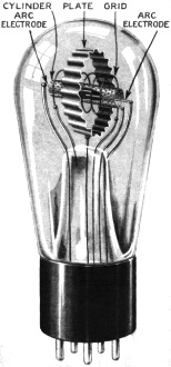
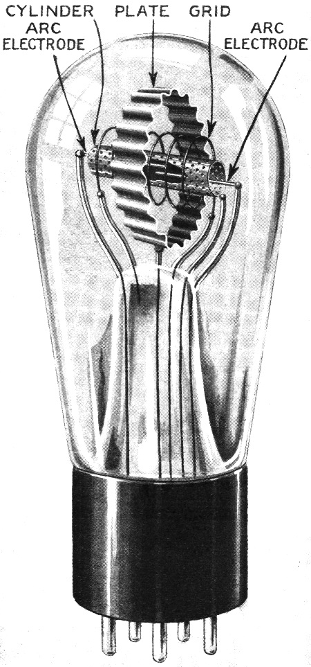
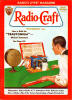
Fig. 1 - Illustration of one type of filamentless tube along
the lines suggested by Dr. Hund at his recent lecture in New York. This tube is
drawn approximately to scale, and the location of all the elements is clearly indicated.
The type of tubes described in this article are not pipe dreams,
but actually have been constructed and successfully demonstrated. While the total
power required to work the tube is slightly greater than a corresponding filament
tube, the extremely long life it enjoys more than compensates for this slight increase
in power. Then again, the necessity for filament transformers is not present. Of
considerable manufacturing importance is the comparative leeway in gas pressure
allowed, and the tube may even function with about 10 mm. of air alone! The materials
used as the elements are not critical, both as to type and purity; a plate, for
instance, may be of iron, and this iron may be either clean or rusty - the results
are the same. It is expected that commercial tubes may be available in about one
year.
Radio-Craft takes pride in presenting a description of one type
of American filamentless tube.
Tubes of various types and classes have been described in this and other publications
since the latter part of the nineteenth century; but, in nearly every case, the
tubes described employed a filament as the primary source of electrons. Ionization
of gas has been suggested as a means of securing electron emission, and a great
deal of work has been done along this line in Germany. We herewith present the first
complete description of an American filamentless tube, recently demonstrated in
New York.
A furore was created at the January, 1933 meeting of the Institute of Radio Engineers
when Dr. August Hund, a member of the research staff of Wired Radio, Inc., discussed
the development and demonstrated the operation of filamentless ("cold-cathode"),
or ionized-gas, tubes. (Based on the fundamental experiments of Dr. Lee DeForest,
nearly thirty years ago, as mentioned in the article, "Soon-The Cold-Cathode Vacuum
Tube," in the May, 1931, issue of Radio-Craft - Technical Editor.) Over 1,000 engineers
listened to every word of this well-known scientist and pioneer in the development
of ionized-gas discharge devices. In a short address, just before the discussion
of Dr. Hund's paper by members of the Institute, Mr. R. D. Duncan, Jr., chief engineer
of Wired Radio, Inc., stated that the primary interest of his company in new tube
developments was in long life, because of the tremendous cost it would be for his
company to service burned-out tubes in the rented receiver system they plan to install
shortly in Cleveland, Ohio.
Uses of Filamentless Tubes
The experimental tubes demonstrated by the Doctor were put through the paces
of oscillation, detection (or demodulation, as the Doctor chose to call it), voltage
amplification, and power amplification. The tubes of the power class operated as
class B, push-push devices. Oscillations were produced by feedback circuits.
A four-tube set (contained in a cabinet of conventional design) demonstrated
beyond a doubt, when music and speech of excellent quality filled the packed auditorium,
that the filamentless tube can rival the filament tube in performance! (A beautiful
lavender glow; sufficiently strong to permit the reading of newspaper print a short
distance away, emanated from the ends of the tubes' cathodes.) A one-tube set gave
loudspeaker volume that would be sufficient for any hotel room.
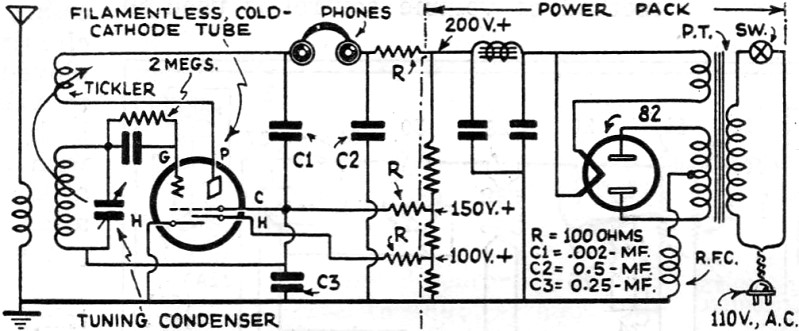
An experimental tube design shown and described is illustrated in Fig. 1;
a schematic circuit of a "1-tube loudspeaker set," designed in accordance with the
engineering data given verbally and via the blackboard by Dr. Hund, is shown in
Fig. 2; a theoretical amplifier circuit is Fig. 3. It must be remembered
that although experimental work is still continuing, commercial tubes are not yet
available, and hard and fast figures cannot be given.
Two general types of tubes have been developed, one of which is a five-electrode
tube that makes use of the conduction of negative ions, while the other is a two-electrode
tube operating on the negative resistance principle involved in the operation of
the Poulsen arc. Both types of tubes have been made to function as oscillators,
amplifiers, modulators and demodulators, and several forms of amplifier tubes working
on both the ionization and negative resistance principles were described, but the
design of greatest interest to the average radio man is the former or "ionization"
type.
The "Uniode" Filamentless Tube
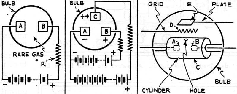
In Fig. 4 we have the first blackboard illustration sketched by the Doctor.
In this elementary form of tube, we have the basis of many already commercialized
devices. A globe with about 10 or 20 mm. of some inert gas encloses two electrodes,
a cathode A and an anode B; a high-voltage battery and limiting resistor R complete
the circuit. This resistor limits the current through the tube, which current otherwise
would reach an excessive value due to the low resistance of the ionized gas.
With the battery current adjusted to a value that is not critical, we have a
glow between the electrodes. The color is pink for neon, and lavender or purple
for helium. This glow is thought to be caused by the collision of positive ions
and electrons dissociated by the highly charged electrodes A and B.
This "uniode" tube can be made to detect, oscillate and amplify; also, relaxation
oscillation has been produced from low audio frequencies to 30,000 kc. (10 meters),
according to Dr. Hund. However, these two-element tubes have serious limitations
when compared to the orderly working thermionic class used in our present receivers,
and, therefore, it was found necessary to modify the design in order to more closely
approximate the performance of filament-type tubes. At the same time, the feature
of unlimited life was obtained. This modification, Fig. 5, is the introduction
of a third element marked C.
How the Diode Cold-Cathode Tube Operates
The dissociation of electrons and positive ions from the rare-gas atom, as explained,
makes it possible to pull great quantities of negatively charged ions and electrons
to the third electrode, which is charged "plus plus" (the Doctor's terminology),
or at a higher voltage than electrode B. We now have one stream of electrons and
ions between A and B, and another to C. In a hot-cathode type diode tube the filament
may be likened to the path A-B, and the internal plate circuit as the electron stream
to C.
So far, the talk had only reviewed the work of previous investigators, continuing
with the remark that as soon as a grid was put between the arc and the plate C,
the grid becomes charged with positive ions and causes it to become inoperative.
This was the starting point for the description of the structural changes which
made the filamentless triode practical.
Construction of the Filamentless Triode
The next blackboard sketch, Fig. 6, showed the introduction of a perforated
electrode in place of C in Fig. 5; the introduction of a grid D and plate E
completed the representation of a triode which may be designed for any service.
The action was explained as follows: Electrons and positively charged ions from
the arc between A and B are accelerated through the perforated cylinder; for purposes
of explanation, only one of the small holes is shown. (See Fig. 1.)
The shielding effect of this positively charged cylinder slows the speed of the
positively charged ions so that there is practically no trace of this trouble maker
in the electron stream between the cylinder and plate. A grid in the electron stream
now affords complete control of the operation of the tube, similar to any triode.
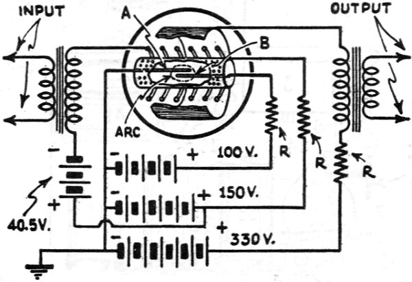
In order to obtain power from the tube, the entire surface of this cylinder,
or "cathode," must be perforated, as shown in Fig. 3. (These holes measure
about 40 mils in diam.) This gives us an electron stream second to none; not even
the best of filament or hot-cathode emitters. Once the electrons are drawn through
this cathode, the operation of the tube is exactly analogous to the operation of
hot-cathode emitters, and the glass envelope, therefore, may contain all the additional
electrodes necessary to produce a diode, triode, screen-grid quadrode, pentode,
and, if the tube industry finds need for such, a septode or heptode.
By placing the grid and plate all the way around the cylinder it was found possible
to take advantage of the electrons coming through all the holes; this is the controlling
factor which enabled the Doctor to design almost any kind of a tube, be it for voltage
or power amplification, or detection or oscillation. The corrugated appearance of
the plate electrode (which very much resembles a biscuit-cutter) is explained when
it is recalled that if it were not corrugated the electrons would tend to be drawn
to that point on the surface of the plate which is nearest the cathode - because
of mechanical asymmetry - and corrugating the plate tends to result in the electrons
being drawn through all the holes in the cathode and distributed over the entire
area of the plate (provided the elements are symmetrically positioned with the usual
commercial tolerances).
Characteristic Data
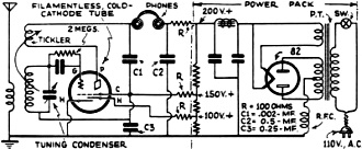
Fig. 2 - Schematic circuit of a one-tube receiver using
the filamentless tube described in this article.
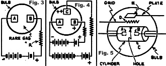
Fig. 3 - A theoretical circuit illustrating the use of the
filamentless tube as an amplifier.
Fig. 4 - Simple circuit of an elementary gaseous two-element
tube.
Fig. 5 - Same as Fig. 4, with a third element, C, inserted
and charged.
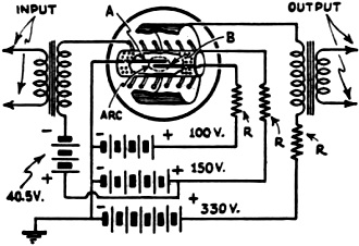
Fig. 6 - Simple schematic of the filamentless tube showing
the use of the holes.
Although it is regretted that curves of the static and dynamic characteristics
of the experimental tubes described by Dr. Hund are not available at the present
time, considerable information may be obtained from the figures given and from known
data regarding the operation of gas discharge devices.
A potential of 100 volts is shown in Figs. 2 and 3 as the value required to produce
ionization between the two overlapping electrodes; this figure, however, will depend
entirely upon individual tube design. The current required to produce sufficient
ionization for operation, in the desired service is another variable factor; in
one tube model this figure was 60 ma. The "power" consumption of this ionized path
(equivalent to the more usual "filament.") is, therefore, 6 watts. In both Figs.
2 and 3 the cathode is shown placed at a potential 50 volts above that required
for normal ionization, or 150 volts; the cathode current consumption will vary with
tube design.
The grid and plate voltages, shown in Fig. 2, are those usually employed
for grid-leak detection using certain types of hot-cathode triodes (zero grid bias,
and 50 volts on the plate with equivalent plate current drain). The grid and plate
voltages, and plate current of Fig. 3 parallel the figures for operation of
a type 71A tube used as an amplifier. As Fig. 2 indicates, it makes no difference
whether the operating potentials for a filamentless tube are obtained from batteries
or a "B" eliminator, provided correct bypassing is secured in the latter instance.
Grid input impedances may run as low as 30,000 ohms and as high as present tubes.
Output impedances can be made to match present tubes so that present transformers
can be used. The power transformer must be designed to accommodate the additional
150 volts required by the ionizing and cathode circuits at the current drain of
the particular tube types.
At the conclusion of the reading of Dr. Hund's paper, it was not necessary for
the President of the Institute to ask for a rising vote of thanks as the audience
showed their appreciation of this amazing development by long and loud applause.
The discussion which followed brought to light several interesting points.
The Discussion
For instance, it was brought to light that some heat is developed by electron
bombardment of the electrodes; however, this heat is carried off through the stem
of the tube by conduction, and does not reach a temperature .high enough, for instance,
to burn the hand.
In answer to another question; it was explained that the material used for the
electrodes did not make much difference. In some tubes the electrodes were made
of iron, while in others aluminum and nickel. The iron could be rusty, oily, and
dirty; clean: electrodes were no better than dirty ones.
The kind of gas used did not seem to make any differences; combinations also
did not exhibit any differences in operation. Chemically pure gas reduced the ionizing
potential from about 100 volts, which was not considered too high, to as low as
35 volts. The amount of gas was usually between 10 and 20 millimeters, but Dr. Hund
said he obtained quite satisfactory operation by using only ordinary air exhausted
to 10 mm., and without the addition of any other gases. (Apparently occluded gases
cause little trouble in a tube of this type, and since high evacuation on expensive
pumps is one of the most costly procedures in the manufacture of present-day hot-cathode
tubes, it follows that a marked saving should be affected in the procedure of manufacturing
cold-cathode tubes.)
The doctor explained to another engineer that the insulation within the tube
was carried right up to the electrodes by extending the glass to the point of contact
with the electrodes. This is done in order to prevent "sputtering" or uncontrollable
sparking from point to point which otherwise occurs in gas-filled tubes.
Although the inquiries of four engineers and the impromptu calculations of another
tended to indicate that the over-all power consumption of a tube of the filamentless
type exceeded that of the filament type, it was pointed out that the practically
"lifetime" longevity of the tube, its low cost of production, its freedom, from
variations in characteristics with relatively large changes in gas pressure, the
absence of a filament winding on the power transformer, the ease of reproducing
tubes having a given characteristic, and the simplification of receiver wiring,
far more than offset the added cost of the increase in high-voltage output necessary
to supply the ionization and cathode potentials and currents. Undoubtedly, this
talk by Dr. Hund has done more to stimulate nationwide interest in the cold-cathode
or filamentless type of tube than any other publicity so far.
Posted January 2, 2023
(updated from original
post on 1/22/2015)
|