|
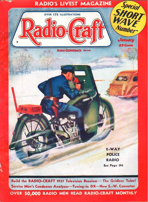
January 1937 Radio-Craft
 [Table of Contents] [Table of Contents]
Wax nostalgic about and learn from the history of early electronics.
See articles from Radio-Craft,
published 1929 - 1953. All copyrights are hereby acknowledged.
|
Assuming the 10 enumerated advantages
of a gridless vacuum tube may be added to the 17 enumerated disadvantages of a gridded
vacuum tube, there are 27 reasons, per author Henri Dalpayrat why one should consider
abandoning the "old style" tubes for his revolutionary concept.
Part 1
of this 2-part series discussed the unavoidably negative features of a gridded vacuum
tube. Part 2, presently, extolls the wonders of a gridless tube. Chief among the
features is the use of "compressor bar" elements that are situated parallel to the
electron flow rather than in series with it. Another major difference is the cathode
element running vertically up the center of the tube and the cathode wraps around
it. If I had to draw a comparison of gridless versus gridded vacuum tubes with semiconductor
devices, the former more closely relates to a field effect transistor (FET) and
the latter to a bipolar junction transistor (BJT). I say that because the compressor
bars' action on the electron flow is to change the concentration (density), effectively
having the ability to cut off the current. Although not related functionally to
the BJT, the gridless tube uses "collectors" to help control the transconductance.
Gridless vs. Grid Vacuum Tubes
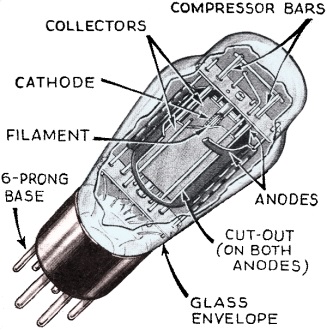
Fig. A - Phantom view of basic gridless tube; note the "compressors."
Henri F. Dalpayrat
Ever since the grid element was first incorporated in a vacuum tube it has been
a dogma that all subsequent tubes be similarly constructed. The author points the
way to a new era, in electron tube designs, in which the previously-discussed disadvantages
of a grid are eliminated by means of a "compressor."
By the simple expedient of arranging "compressor" elements to control by electronic
means the electron emission from cathode to anode, a radically new design in electron
tubes is effected. Coincidentally, many new and important functions are made available;
one of the most outstanding of these is automatic noise suppression; in this design,
both the above- and below-signal-level interference voltages are counteracted.
Part II
In the preceding issue of Radio-Craft, an enumeration of several disadvantages
inherent in all grid tubes, were discussed, to point the way to much-needed improvements
in electronic amplifying devices.
The new electronic principle described in the present article, and discussed
in connection with gridless tubes, indicates the possibility of designing greatly-improved
radio vacuum tubes without adhering to the conventional arrangement of electrodes.
 "Grid" Tubes Fundamentally Unsound "Grid" Tubes Fundamentally Unsound
Contrary to popular belief, the standard "grid" tubes now available in the industry,
although highly perfected, still have many objectionable features which cannot be
corrected as long as grids are used, and which cannot be overcome by electrical
circuit designs.
The source of most of the difficulties now found in thermionic amplifiers is
in the tubes themselves, and it seems more logical to produce new and better tubes,
rather than to improve an old and inefficient electronic technique; even though
it is now generally conceded that much is to be gained by attempts to "modernize"
it.
The average radio engineer, accustomed to think in terms of "grids," is inclined
to take grids for granted, or as almost indispensable; though a little thought on
this subject, along new theoretical principles, will disclose innumerable and important
advantages derived by the total elimination of all grids!
The great number of new electrical circuits possible with the new type of "gridless"
tubes (here illustrated in theory and practice) open up new fields for experimentation
and invention, independent of the patent restrictions or technical limitations usually
allied with well-known, well-developed standard tubes.
The Design of Gridless Tubes
One important feature of this invention is the complete elimination of the grids
and their disadvantages.
Another object of the principle disclosed in these illustrations and data that
follow, and the novel combinations of new electrodes in the devices, is to provide
new types of vacuum-tube designs for a wider range of applications and, generally,
greater usefulness than the now well-known vacuum tubes using a number of solenoid
wire grids, or their perforated equivalent, concentrically positioned around a heated
cathode emitting electrons.
Referring to the drawings, Fig. A shows a new type of amplifying vacuum
tube, or thermionic relay, with an evacuated envelope made of glass or metal (shown
in this figure as glass) on a base having contact prongs connected within the tube
to separate or similar electrodes. The centrally-located cathode sleeve is coated
externally with rare-earth oxides and heated internally by a filament. Two plates
in close proximity to the cathode are shown as "collectors," and two wires (rods
or hollow metal cylinders) placed in spaced parallel relations with the cathode
and "collectors" are the "compressor bars," within the anodes or plates, as shown
sectionally in Fig. 1.
The anodes may be separate plates, either electrically connected or insulated
from each other, or formed of a single tubular plate having its facing surface plates
stamped out, to decrease capacity coupling between the anode and. collectors.
Figure 1 (A, B and C) shows the arrangement of the tube electrodes mentioned,
as seen endwise. The filament-heated, coated cathode is emitting electrons which
are repelled by negatively-charged electrodes or compressor bars; thus forming 2
electron beams which are each attracted and collected by the positively-charged
collectors; these have their positive potential regulated to be much lower than
that of the anode plates. The voltage on the "collectors" is made small enough to
allow the compression of the stream of electrons by the "compressors"; but also
high enough to establish a constant electronic emission to the "collectors" or absorption
electrodes.
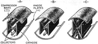
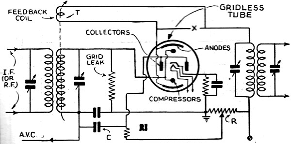
Fig. 1 - Approximate representation of gridless tube operation.

Fig. 2 - Experimental circuit in analysis of gridless tube
operation.
Figure 1A shows how a high negative charge, applied on the compressors, directs
all electrons towards the central portion of the surfaces of the collectors. The
combined positive charge of the collectors and negative charge of the compressors
completely prevents any electrons from reaching the anodes. Note the width of the
electron beams, spreading over the surfaces of the collectors; in Fig. 1A;
while Fig. 1B shows how these electron beams spread in cross-sectional areas,
and impinge upon a larger portion of the collector surfaces when the negative charge
of the "compressors" is decreased.
Figure 1C shows how a further decrease in negative potential of the compressors,
or even the application of a positive charge on them, reduces the compression of
the beams of cathode electrons, and allows them to spread over and beyond the surfaces
of the collectors; thus allowing electrons to reach the anode plates in the form
of 4 electron beams. These beams vary in electronic density according to the voltage
variations applied on the compressors, which control the direction of the cathode
electrons towards the collector plates, and vary the number of electrons either
absorbed by these collectors or passing between the collectors and compressors to
be received by the anodes.
Gridless-Tube Circuits
Figure 2 shows how an individual A.V.C., per stage, can be obtained with the
electron- beam compressor tube described above. In this I.F. (the same principle
is applicable at R.F. or A.F.) amplifier, the signals are applied on the compressors,
varying the electrons passing through to the anode. The D.C. potential applied
on the collectors is obtained through a potentiometer R and a signal-load ohmic
impedance high-resistance) R1. When the signal voltage variations, or excessive
noise impulses, rise above the A.V.C. signal level, the positive potential of the
collectors is increased through capacity C. The positive voltage, increasing in
these collectors, absorbs a greater number of electrons from the cathode; thus diverting
electrons from the cathode to the anode streams, and decreasing automatically the
amplification of the tube for only the excessive amplitudes, as adjusted by the
positive absorption potential obtained through R.
The addition of regeneration to this circuit through a tickler coil T, connected
in the anode circuit at point (X) can be advantageously utilized for greater sensitivity,
improved selectivity, or larger power output, or accentuation of certain modulation
frequencies; while the voltage-controlling functions, previously described, enable
this circuit to provide stable and constant automatic regeneration, a feature unusually
useful in short-wave reception.
The foregoing described only a few possible applications, such as individual
(per stage) automatic volume control, automatic regeneration control, and a combination
diode and power output amplifier tube. Other circuits, such as automatic volume
control and noise suppression controls, incorporated in each stage of a receiver,
in order to produce a practical "noiseless" or "static proof" receiver, will be
described, exclusively and for the first time, in a future issue of Radio-Craft.
Referring again to the advantages of "gridless" tubes, and more particularly
to the type invented by the writer and described in this article, a number of advantages
will be given below.
Advantages of Gridless Tubes
It is one purpose of this invention to eliminate solenoid wire grids, and the
method of passing electrons through spaces between wires, or slots, or small perforations
in any controlling electrodes. Another purpose is to simplify the mechanical construction
and assembly of parts in tubes, while providing stronger, more rigid structures,
and insuring the manufacturing production of tubes having uniform characteristics.
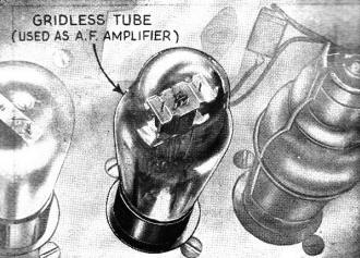
Fig. B - Actual gridless tube in an experimental receiver.
Still another purpose is to greatly decrease interelectrode capacities, and to
render practical these tubes for the faithful amplification of audible frequencies,
or the amplification of very short waves, or the generation of constant oscillations,
etc.
The "gridless" design also provides a new vacuum tube, having inherent self-limiting
amplification properties, and/or self-selecting amplitude-selection properties,
or automatic current or voltage stabilizing properties, in addition to their normally
intended functions such as detection, rectification, and/or amplification.
There are many other important advantages to be obtained by applying the "gridless"
principle of construction to tubes of all types. Some of these features are listed,
numerically, as follows.
(1) Combine, in a simple manner, several functions in one electronic device,
without one function interfering with another.
(2) Permit the manufacture of simple, inexpensive, small tubes, practical for
short-wave operation, and capable of delivering (as working models have proven)
stable, constant, undistorted and highly amplified current.
(3) Provide new tube designs, especially applicable to power output-tube operation
and capable of delivering relatively high undistorted power output, with a minimum
of positive voltage applied on the main output anode.
(4) Reduce or eliminate internal vacuum-tube noises, which are due to electronic
bombardments upon electrodes, or to unwanted electronic reflections or uncontrollable
electronic emissions.
(5) The reduction, or the elimination, of currents in certain electrodes, in
order to minimize a type of output current distortions caused by these electrode
currents.
(6) Inherent ability to limit either their own output current automatically,
within any fixed range of variations, or unwanted signal or noise amplitudes, either
below or above a given intensity level, as determined by adjustable electrical circuit
constants-thus producing an "anti-noise" tube!
(7) Possibility of modulating several electron beams similarly and simultaneously,
or else differently and independently, as desired to utilize their various outputs
for a common purpose or for individual and different purposes.
(8) Production of (relatively) very short electron beams of the full and complete
cathode electronic emission, without resorting to the use of so-called "electron
gun" or other electrical means well-known to the art (which. however, are unable
to cause the utilization of the full cathode emission).
(9) Possibility to cause purposely the liberation of secondary electrons, by
coating certain electrodes with appropriate rare earth oxides; and to utilize the
secondary emission produced by primary electron impacts thereon to obtain a higher
voltage and/or current amplification.
(10) Another new and advantageous feature (available in one design) is a novel
type of controlling electrode, shaped and positioned in such a manner as to divide
an electronic emission, radiating uniformly around a cathode, into a number of electron
beams; while exerting electrostatic pressure upon all these beams simultaneously
or independently.
There are many more features and advantages to be found in the radically-new
"gridless" pri-ciple of operation, and tubes that, by means of "compressor" electrodes,
utilize this principle of operation; but space does not permit further elucidation
at the moment. However, the writer will be glad to answer any inquiries, concerning
the gridless tube, if these inquiries (addressed in care of Radio-Craft) are accompanied
by a stamped and return-addressed envelope.
Posted February 28, 2023
(updated from original
post on 12/3/2015)
|