|
December 1947 Radio-Craft
 [Table
of Contents] [Table
of Contents]
Wax nostalgic about and learn from the history of early electronics.
See articles from Radio-Craft,
published 1929 - 1953. All copyrights are hereby acknowledged.
|
In most instances the method
and materials have changed over the years, but fundamental principles of writing
and reading data to and from magnetic media are the same today as when this article
was written in 1947. If you find that your lexicon of technical jargon lacks terms
such as coercivity
and remanence,
then you might want to invest a few moments reading this short article that appeared
in Radio-Craft magazine. I realize most regular RF Cafe visitors won't be interested, but
hopefully someone, somewhere, searching for this information will now be able to
find it. Thanks for your indulgence.
Part I, "A Modern View of Permanent Magnet Theory," appeared in the October
1947 issue and Part II, "Benefits of Tape Recording," appeared in the November
1947 issue.
Magnetic Recording - Recorder Design
Part III of a series, the first two parts of which were headed Magnetism. This
part deals with recorder design. Next will be construction of a practical tape recorder.
By A.C. Shaney*
*Chief Engineer, Amplifier Corp. of America.
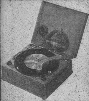
Fig. 1 - The Mail-A-Voice uses magnetic discs. Courtesy
Brush Development Corp.
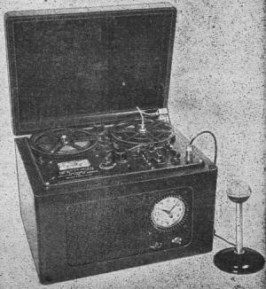
Fig. 2 - This machine records 12,500 cycles. Courtesy Amplifier
Corp. of America
One of the most important elements in any magnetic recording process is the magnetic
carrier (the material upon which the magnetic modulations are impressed or recorded).
Magnetic carriers which have been used successfully to date include metallic ribbon
and wire, nonmagnetic ribbon and wire plated with special magnetic coatings, and
magnetically coated and impregnated paper and plastic tapes. Early experimenters
successfully applied magnetic modulation to a magnetically coated cylinder. A magnetic
recorder and play-back device which is now available (Fig. 1) utilizes magnetically
coated thin paper discs. This list is merely suggestive and by no means exhausts
all the possibilities. For example, it should be both economical and practical to
coat or impregnate magnetically plastic or cotton fiber thread or other artificial
fiber.
The actual magnetic properties of the magnetic carrier determine, to a considerable
degree, the overall performance characteristics of the recording and playback system.
They also play an important determinative factor in the design of all other essential
elements and auxiliary components used in both the magnetic recording and playback
processes.
Many early and highly qualified technicians experimenting with magnetic recording
failed to evaluate properly all effects which were normal functions of carrier characteristics,
and as a result came to erroneous conclusions. For example" it was believed (during
1932, that it was necessary to run a magnetic carrier at a speed of 393.7 inches
per second to obtain a frequency response up to 5,000 cycles. As a result, it was
fallaciously concluded that the necessity for the high speed "restricts the application
of this recording method to reproduction in the speech range." Today in contrast,
a commercially available unit (Fig. 2) is capable of recording and reproducing
up to 5,000 cycles with a carrier speed of 4 inches per second - a reduction in
carrier speed of nearly 100 times without affecting frequency response, attaining,
at the same time, many other desirable improvements in noise reduction, increased
dynamic range, and lower distortion! Nine thousand cycles has been recorded and
played back at a carrier speed of 7 1/2 inches per second, and 12,500 cycles has
been attained at a tape speed of 15 inches per second. (Magnetically coated paper
tape was used to attain the indicated results.)
The rate of progress in the art of magnetic recording can be measured by the
carrier speed of the magnetic medium employed. Slow speeds (with desired frequency
response) indicate greater economy of the magnetic medium and longer playing time
for a given length and cost of material
Progress in this respect has been little short of phenomenal. For example, in
1932 118,000 feet of wire was required for a 1-hour program reproducing up to 5,000
cycles. In 1943 the same program quality and duration could be maintained with 11,000
feet of wire. By 1946, it took only 1,250 feet of coated tape to duplicate the same
program!
All students of radio have been correctly impressed with the idea that the rate
of radio wave propagation (radio carrier speed) is constant (300,000,000 meters
per second). As a result, it is simple to calculate wave length - the distance through
which current will travel within one cycle - from the following well-known formula.
λ = k/f
when λ = wavelength, f = frequency, and k = carrier speed (186,000 miles
per second or 300,000,000 meters per second).
In magnetic recording, the carrier speed is not a fixed and unvarying constant.
In fact, as previously explained, there is a strong tendency to continually decrease
its speed without affecting over-all response. As a result, the magnetically recorded
wavelength of a given frequency will be a function of the magnetic carrier speed
and can be found from this simple expression:
λ = s/f
when s = magnetic carrier lineal speed.
Thus a 5,000-cycle signal when magnetically recorded on a tape running 7 1/2
inches per second will have a wave length of 1.5 thousandths of an inch. Similarly,
a 5,000-cycle signal recorded at a carrier speed of 4 inches will have a wave length
of 8 ten-thousandths of an inch.
When it is realized that each complete wave length has 4 phases (see Fig. 3),
evidently each phase of 8 ten-thousandths of an inch wave length will be only 2
ten-thousandths of an inch long (approximately 5 microns). We begin to get an idea
of the minute dimensions involved in attempting high-frequency magnetic recording
on slow-moving media.
Carrier speed stability
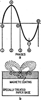
Fig. 3-a - Four phases of sine wave. 3-b - Enlarged cross
section of paper tape to show internal and external magnetic flux lines.
A casual examination of the formula (2) relating wave length to speed and frequency
indicates that if the magnetic wave length is constant (and it is, if a fixed frequency
has been recorded at a constant speed) the reproduced frequency will be directly
proportional to lineal speed. If the lineal speed of the magnetic medium should
vary for any reason whatsoever, the reproduced frequency will similarly vary. This
produces a noticeable variation of frequency when sustained tones are reproduced
and resembles the turntable "wow" common to disc recording and reproducing systems
which do not employ absolutely constant-speed turntables. To minimize any instantaneous
speed variations, it is important to avoid eccentricities in any of the driving
members involved in pulling the magnetic medium past the playback head. A correctly
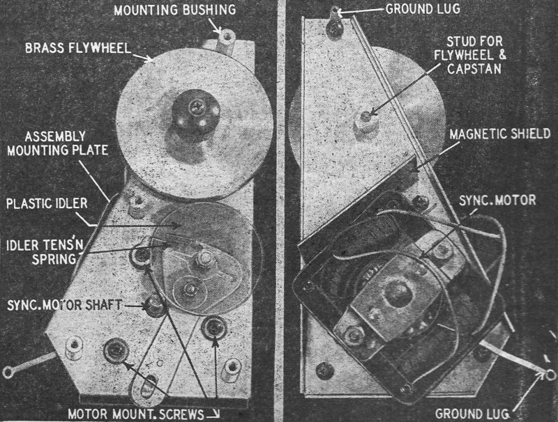
designed flywheel should be used to smooth out cyclic pulls common to "constant
speed" synchronous "motors. A correctly designed capstan drive and flywheel is illustrated
in Fig. 4.
The load applied to the driving motor should be constant. Bent reels or spools
which scrape either the recording medium or adjacent surfaces are the most common
cause of frequency variations in a properly designed mechanism. An idea of the desired
constancy of linear speed may be gained from the already established data which
indicates that an average listener can detect frequency deviations in the order
of 3/10 of 1% (3 parts in 1,000) within the frequency range of 400 to 5,000 cycles.
Therefore, instantaneous lineal speed variations should be no greater than ± 0.1%
(which allows a variation of 2 parts in 1,000).
Magnetic carrier compliance
Early experimenters who attempted to increase the high-frequency response of
magnetic recording systems by increasing wire speeds were bothered by pronounced
variations in signal level mainly caused by wire "flutter."
A stiff wire travelling at high speed will tend to assume some natural period
of vibration dependent upon its thickness, tautness, and the distance between its
supports. Flutter (a transverse vibration) produces a minute frequency variation
"wow" (because a slight change in lineal speed takes place), but more important,
it introduces a varying pressure against the recording head which in turn changes
the air gaps between the magnetic medium and its pickup head. These minute variations
produce appreciable high-frequency level fluctuations characteristic of flutter.
Steel tapes travelling at high speeds are similarly afflicted. Paper and plastic
tapes, - because of their increased compliance and slow speeds - are more easily
passed by the pickup head with negligible flutter effects. On the other hand, their
increased compliance makes it necessary to use pressure fingers to keep the tape
pressed, at a relatively fixed pressure, against the recording and playback heads.
Dimensional stability
When discussing lineal speed stability and its relation to "wow," it was assumed
that a magnetically recorded fixed-frequency signal would maintain a fixed wave
length. This is true as long as the wire or tape doesn't stretch. If stretching
does take place, because of temperature and humidity changes between the recording
and playback process (and it may, because of the tensions or pull applied to the
medium during recording, rewinding, and playback), we then have a new variable to
consider.
A simple transposition of formula (2) produces
s = λf (3)
which indicates that if the speed remains constant, the reproduced frequency
is inversely proportional to wave length. In other words, if the magnetic medium
stretches the wave length increases and reproduced frequency decreases! This effect
will not be noticeable as long as the "stretch" or dimensional stability is within
± 0.1%. Plastic tapes and thin wires naturally will have some tendency to stretch.
The paper base used for coated tape is made of carefully selected material and treated
by prestretching for improved dimensional stability.

Fig. 4 - A correctly designed "tape puller" for magnetic
recording and playback devices.
As expected, one of the most important elements in magnetic recording and playback
is the actual magnetic and physical properties of the magnetic carrier. In a magnetic
coated medium, the coating itself, and not the base, plays the most important role
in the process.
Some of the more critical factors which determine the efficiency, noise, response,
constancy of output, overload characteristics, and velocity of the carrier include
it coercivity, remanence, particle size, binder, dispersion, chemical composition,
surface smoothness, and coating thickness.
Each of these characteristics has a profound influence upon the over-all characteristics
and performance of the recording and playback system.
A brief. discussion of these factors together with the design details of a suitable
magnetic recording amplifier will be covered in the next issue.
Two transpositional errors occurred in the October installment of this series.
In comparing the conductivity of electric and magnetic circuits, the formulae should
have been:
G = I/E
μ = B/H
G = conductance in mhos
E = e.m.f. (volts)
I = current (amps)
μ = permeability
H = magnetomotive force (oersteds)
B = magnetic flux (gausses)
Posted April 8, 2022
(updated from original post on 9/9/2014) |