|
October 1945 Radio-Craft
 [Table of Contents] [Table of Contents]
Wax nostalgic about and learn from the history of early electronics.
See articles from Radio-Craft,
published 1929 - 1953. All copyrights are hereby acknowledged.
|
 "Morale Radio" sets were manufactured by
many companies and provided to service men for entertainment and hearing news from
back home and around the world. Unsubstantiated sources claim American companies
were paid cost + 15% for each set. Other countries made similar "Morale Radios"
for their troops, or procured sets from elsewhere and made necessary modifications
to suit their format. Not a whole lot of information can be found about them on
the WWW, and finding a photo of one of the German Wehrmacht radios with the Swastika
and eagle on it is darned near impossible, other than the one shown in this 1945
Radio-Craft magazine article. Part of the reason for the scarcity is the
German people's desire to destroy as much of the
Nazi (National Socialist
German Workers' Party) history as possible both to put the horrible era behind them
and to help reduce the potential for war crimes to be traced back to them. The
Swastika is a particularly
despised symbol of the regime and is now outlawed in Germany (other than in museum-like
settings). "Morale Radio" sets were manufactured by
many companies and provided to service men for entertainment and hearing news from
back home and around the world. Unsubstantiated sources claim American companies
were paid cost + 15% for each set. Other countries made similar "Morale Radios"
for their troops, or procured sets from elsewhere and made necessary modifications
to suit their format. Not a whole lot of information can be found about them on
the WWW, and finding a photo of one of the German Wehrmacht radios with the Swastika
and eagle on it is darned near impossible, other than the one shown in this 1945
Radio-Craft magazine article. Part of the reason for the scarcity is the
German people's desire to destroy as much of the
Nazi (National Socialist
German Workers' Party) history as possible both to put the horrible era behind them
and to help reduce the potential for war crimes to be traced back to them. The
Swastika is a particularly
despised symbol of the regime and is now outlawed in Germany (other than in museum-like
settings).
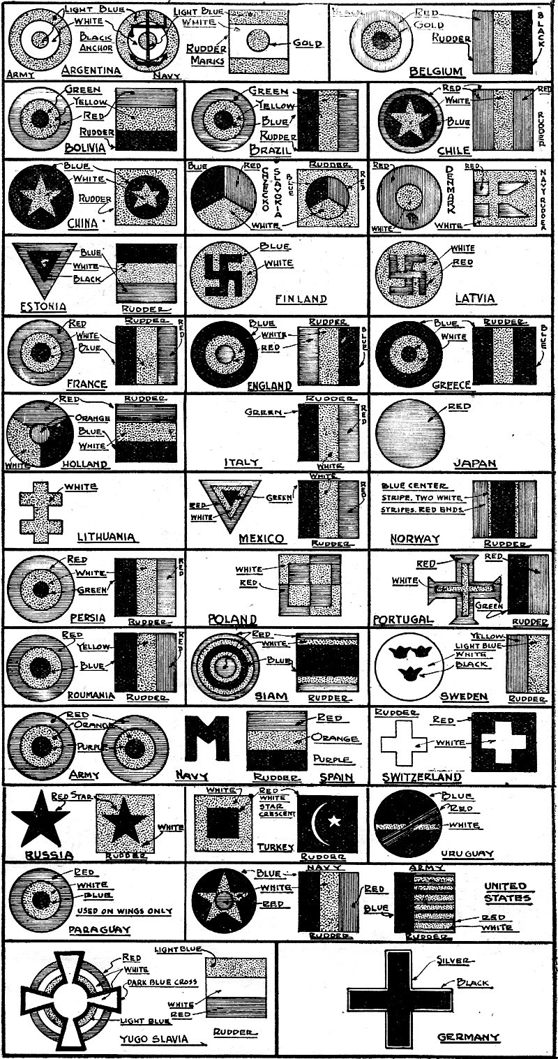
Interestingly the Germans were not the only country that used a
Swastika for military markings (click thumbnail above). I was surprised to find
in a 1930s
Flying Aces model airplane magazine that the European countries of Finland and Latvia used Swastika insignia.
Nazi Morale Radio - Presents Interesting Contrasts to U. S. Sets
By Alan Jay
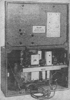
A rear view of the Wehrmacht radio showing components.
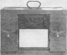
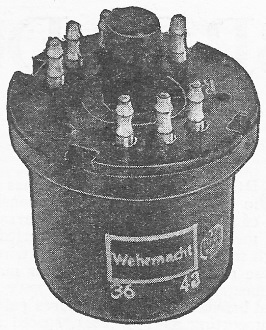
The front view of the Wehrmacht radio.
The Nazi Air Force, in a last minute effort to boost the morale of the German
soldier, supplied him with the latest word in radio reception. It is a three-band
"morale receiver," vaguely similar to R-100/URR U. S. Army "morale" set, and was
distributed to the soldiers for their entertainment.
The receiver was "liberated" by an 8th Air Force member and given to Sgt. Joseph
Ferrara of the U. S. Army Infantry. It operates on either dry cells, wet batteries
or 120 volts D. C., and is housed in an Army cabinet, portable style. When it is
considered that the Germans have worked with "ersatz" materials for so long and
have found them so "satisfactory," many features of its design are noteworthy. On
the other hand, there are more bad points than good from the customary American
standpoint.
The speaker has an unusually large magnet, when its total size is considered.
The cone is approximately 6 inches, and the magnet is 2 inches in diameter and 2
inches in depth. The cone is supported by an "independent" spider such as has been
found on some of our speakers. Adjustments in centering are accomplished on the
outside, by means of two bolts fastening the spider to the speaker frame. A dust
cover is placed over the speaker. This is nothing more than a piece of cloth, wrapped
twice around the frame and tied in the rear. The voice coil leads are covered with
what appears to be silken braid, and are brought through a rubber bushing or grommet.
This is radically different from our standardized method of bringing them to insulated
lugs on the speaker frame and then extending another pair of leads to the output
transformer. The German method seems fraught with disaster, for, since the leads
are exposed, a slight pull or accidental tug on them might carry the voice coil
out of the cone to a place where it could readily be examined visually for defects
in construction!
All Values Indicated
All condensers and resistors are marked with their values. This is considerably
better than the system now in effect here (as has been brought out in numerous articles).
On the other hand, there is an attempt in this construction to use altogether too
many chassis. The electrolytic condensers are mounted on an independent chassis,
as are the trimmer condensers. The bracket on which the electrolytics are mounted
is easily seen in the rear-view photo. An entire network of condensers and resistors
for several circuits is mounted in a little sheet-metal case. Leads to the proper
circuits are then brought out through bushed holes in the sides of the cans. While
this might facilitate assembly it does nothing towards making servicing any easier.
Trimmers for all circuits as well as the padder condensers are all mounted on one
strip. This includes the trimming condensers normally found on the top of the variable
condensers in our receivers. The R.F. and antenna coils are mounted on the back
of these strips. All coils in this receiver are wound on what appears to be plastic
or possibly polystyrene forms, and are all tuned with an iron core (permeability
tuning). The variable condenser is enclosed in an aluminum can, possibly. This tends
to prevent tampering with the condenser and at the same time, both shields the variable
condenser and protects the plates from possible damage. A fibre or plastic chassis
is used instead of a metal one.
One of the metal tubes from the receiver.
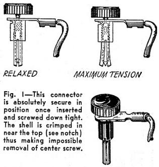
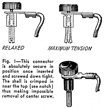
Fig. 1 - This connector is absolutely secure in position once
inserted and screwed down tight. The shell is crimped in near the top (see notch)
thus making impossible removal of center screw.
The I.F. coils are wound on plastic forms. Low-temperature-coefficient condensers
similar to some of American manufacture are mounted on a terminal strip inside of
the can and connected across the primary and secondary of the coil respectively.
These are fixed condensers rather than adjustable, as our I.F. trimmers are. The
coils have an iron core in the center which can be adjusted through a hole provided
for this purpose in the side of the can.
The can itself is made of heavy-gauge aluminum and is fastened by in an unusual
manner. A slot is cut in the top of the can to accommodate a semi-circular strip
of fibre. This in turn has a small rectangular slot cut into it. A fibre wedge is
inserted into this slot and driven in until the can is fastened securely. The good
feature of this is its easy accessibility. Just knock out the wedge, and the I.F.
coil is available for inspection. This same wedge principle is used throughout as
a convenient method of fastening without the use of nuts and bolts, and it is applied
to the battery plugs as shown in the illustration., Fig. 1. As the knob is turned
in, after the pin plug is inserted into the battery terminal, the wedge spreads
the sides of the split banana plug, forcing them into tight contact with the sides
of the battery terminal jack. The entire set can be lifted by this plug once the
connection is tightened. This would seem to constitute a considerable improvement
over our conventional snap-on buttons, binding posts, etc.
The tubes are the most interesting feature of this set. They are metal tubes
roughly similar to ours in appearance, but approximately one-half the height and
twice the diameter. The pins, as can be seen in the diagram, are of the locking
type, yet the tubes are surprisingly easy to remove. This is accounted for by the
fact that they also employ a wedge principle. They are tapered gradually instead
of sharply as in the locking pin on American octal tubes. The tubes are mounted
on felt cushions to protect them from shock, as can be seen in the photograph.
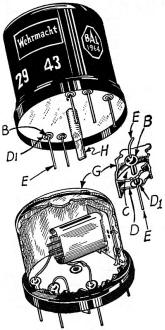
Fig. 2 - Wehrmacht tube. B - Glass insulating bead. C - Upper
platform. D - Lower platform. D. - Metal-to-glass header ring. E - Lead to interior
elements. G - Shell. H - Copper tube shown crimped after sealing-off.
An unusual feature is the total lack of glass in the tubes, with the exception
of the seal of the pins to the base. Fig. 2 shows the method. This system has been
used in special American war-time tubes, but is not yet commonly employed here.
The tubes are evacuated after the assembly of the entire tube has taken place, with
the exception of basing. A copper tube is brought out from the base, and the evacuating
pumps attached to this. The air is then apparently pumped out and the copper tube
sealed and crimped. A metal deflector plate is welded to the top of the inside crown
of the tube. The elements, as is common in European manufacture, are laid on their
sides, in contrast to our method of standing them up.
The line is fused in all cases, but the customary interlocking switches are conspicuous
by their absence. A giant loop antenna is enclosed in the back cover of the "box"
or cabinet.
Band coverage is from 15 to 50 meters; 200 to 550 meters, and 800 to 2000 meters,
in addition to provision for phonograph attachment on the side of the carrying case,
and a phono position on the band-change switch.
The dial is unusual in comparison to our dials. All stations are listed by the
names of the cities or towns of origination. Calibrated markings on the top and
bottom in meters merely serve as indicating devices rather than dependent tuning
markings. The dial is made of glass. painted black on the inner surface with cut-outs
where the station indicator windows appear. It is backed with a white drop, for
easy reading. The grille cloth on the speaker is of a cream color which contrasts
sharply but neatly with the black plastic trim and dial contrasting almost ludicrously
with the drab, army-gray field case.
Posted August 2, 2021
|


