|
June 1931 Radio-Craft
 [Table
of Contents] [Table
of Contents]
Wax nostalgic about and learn from the history of early electronics.
See articles from Radio-Craft,
published 1929 - 1953. All copyrights are hereby acknowledged.
|
Here is yet another treatise on
the subject of reactance and resistance. Considering that the date on this Radio-Craft
magazine is 1931, it was probably amongst the first to publically discuss such newfangled
topics outside of a formal university setting. The layman just was not accustomed
to being bothered with such esoteric concepts. After all, not many decades previous
a person might be burned at the stake for exercising such witchcraft as speaking
of "imaginary" numbers as is required for a complete analysis of alternating circuits.
This article, however, does not actually get into complex numbers, but future ones
did.
The Whole Ohm Family - R, X and Z
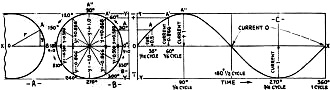
Fig. 1 - Left, a single "sine." Middle, a flock of stiles,
each corresponding to its respective anole. Right, the conventional "sine wave"
showing how it corresponds to the circle, and how the current (or voltage) fluctuates
during the different portions of an A.C. cycle.
A Simple Explanation of Reactance and Impedance
By Hal Wyman
There are several different kinds of ohms - as many readers already know, and
others have suspected from some of the theoretical formulas which they have encountered
in their studies as Service Men, set builders and experimenters. That is to say,
the ohm is not merely the unit of resistance (R), which, under a constant potential
of one volt, allows one ampere to flow; but it is also the unit of reactance (X)
and of impedance (Z). In order to explain the latter terms, let us first consider
the fundamental nature of an alternating current; and, in connection with the latter,
the common expression, a "sine-wave."
The Sine Wave
The sine is the distance between two sides of an angle; measured in terms of
the length of one side, on a perpendicular dropped to the other side. See Fig. 1A,
in which the line OA is the radius of a circle. Its length is r; the length of the
line AB dropped from A perpendicularly on OB is y, then the sine of the angle between
OA and OB is y/r. It is customary, in calculations, to take the length of the radius
OA as 1; in which case, the sine will always be represented by a fraction the greatest
possible value of which is 1.00.
For every possible angle, there is therefore a corresponding ratio called its
"sine." The angle may be carried beyond 90°, around to 360°,. and it may
be increased still further as the radius continues to revolve around 0; but the
numerical values of the sine will repeat at every quarter turn though alternately
positive and negative. Similarly, in radio graphs, where alternating voltage and
current are represented by curves, different polarities of voltage and directions
of current flow are indicated by the spaces above and below a zero line drawn horizontally
through the figure.
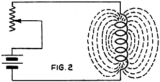
Every conductor (even a straight wire) carrying all electric
current creates a magnetic field, as indicated at the right.
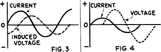
Inductance makes current "lag" behind voltage, as at the left:
capacity makes current lead the voltage, as at the right.
In Fig. 1B, we have a circle in which a radius is revolving around the center
0, like the hour hand of a clock but in the opposite direction here; the height
y of its end A above the zero line X-X, indicates the value of an alternating current.
If the maximum value of that current is taken as 1, when the radius is pointing
straight up, its value at any other moment will be indicated by the sine of the
angle through which the radius has move
But, in drawing a graph like this, we make it difficult to measure the movement
of OA after it has completed the first revolution; and so, to represent an alternating
current, it is customary to suppose that the center of our circle is moving steadily
along the line X-X (as in Fig. 1C. Then we call determine the time during which
the alternations have been taking place, by measuring straight along X-X, which
represents time. At the same time, measuring parallel to the line Y-Y, we determine
current values which, in a true sine-wave, will be in exact proportion to the sine
of the time-angle, or clock-hand, of Fig. 1B. This is called "plotting amplitude
against time."
When the clock hand of Fig. 1B passes 90° (which represents the first
quarter of an alternating-current wave) it begins to come closer to the line X-X;
and when it is right on the line again, zero current is represented. As the moving
hand gets farther from this line, the current again increases; but it is reversed,
as compared with its former polarity. When it gets to 270°, the current is at
its negative maximum; and when it is again 0deg, having completed 360° of turn,
current is again zero, and the first cycle is over.
The same conditions are represented, but by a line which is pulled out into a
"sine wave," instead of by a circle, in Fig. 1C. If we are speaking of 60-cycle
current, the time represented by this curve is 1/60 of a second; if we are speaking
of 600-kilo-cycle current, the time represented is 1/600,000 of a second. But, in
either case, if we are dealing with pure sine-wave A.C. voltage, the curve will
be of the same shape.
The Effect of Inductance
For the moment we will leave our pretty pictures and attempt an explanation of
the term inductive reactance - pausing, of course, for a brief definition of the
word inductance. Suppose that we have constructed a coil of wire wound around either
an air core or on a pile of iron laminations, and connected as in Fig. 2. Magnetic
lines of force are set up - our coil has become an electromagnet. Now this inductive
action will not be purely external, but there will be also interaction between the
turns of wire within the coil itself. The strength of the magnetic field is proportional
to the number of turns and to the current flowing. If the current is varied, the
strength of the magnetic field will also vary in direct proportion.
It is only when the current is changing that this secondary effect, due to the
common linkage of the turns, takes place. While the current is changing, Lenz's
law informs us, the induced E.M.F. or voltage acts in such a way as to oppose the
change which is taking place. Mark the fact that the direction of the current's
flow (whether positive or negative) or its magnitude have nothing whatever to do
with this - it is the rate of change in which we are interested.
Look again at the curve in Fig. 1C, and you will see that the current's
magnitude is continuously changing, except at the instant in each half-cycle when
the maximum positive or negative value is reached.
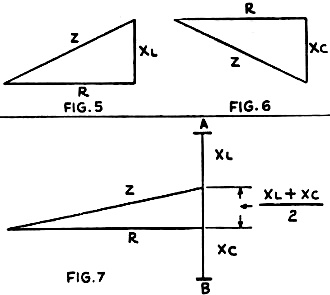
Graphic methods of computing impedance; left upper, from resistance
and inductance, right upper, resistance and capacity. Below, the resultant of all
three factors.
Since the inductive effect is at maximum when the "rate of change" is greatest,
we may assume that the opposing E.M.F., due to the inductance of the circuit, is
at its peak when the current wave is passing through its zero value; and we can
plot a curve to this effect as in Fig. 3. The "peak" value of the current is
as shown by the curve, while the R.M.S. (root-mean-square) or effective value is
but 0.707 of the maximum (ordinary A.C. meters read R.M.S. values.)
At any instant the slope of the current curve gives the rate at which the current
is changing; and it can be seen that the slope is steepest a t the points where
the current crosses the zero line. We may plot the dotted "sinusoidal" line shown
in the Fig. 3 as representing an arbitrary relation between the current and
the "back" or "counter" E.M.F. in an inductance coil of L henries.
Since the back E.M.F. is defined as being exerted in a direction opposing the
current change, we also have shown the back E.M.F. as negative in value while the
growth of current is in the positive direction. The curve of this induced voltage
(the back E.M.F.) is seen from the figure to be just one quarter-cycle out of step
with the current; and we say that it is out of phase by 90 degrees, and that the
current "lags the voltage" or that the voltage "leads" by 90 degrees. This brings
us up to the problem of phase difference from which we will beat a hasty retreat
for the moment.
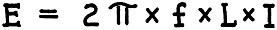
If the frequency in cycles is taken as f, the voltage induced by the
changing current is equal to 6.2832 times f times the inductance in henries
times the current in amperes:
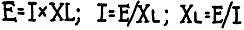
This leads us back to Ohm's Law for direct current; and we will find that, with
the frequency set at a single value, the equations are parallel to those of Ohm's
law but with XL (the inductive reactance - 6.28 f L) taking the place of
R; so that just as simply in the case of direct-current calculations:
(To be continued in July Radio-Craft)
Posted July 19, 2023
(updated from original post
on 9/15/2015)
|


