|
August 1945 Radio-Craft
 [Table
of Contents] [Table
of Contents]
Wax nostalgic about and learn from the history of early electronics.
See articles from Radio-Craft,
published 1929 - 1953. All copyrights are hereby acknowledged.
|
Good power supply design
has always been key to good system function. As with so many other topics in
electronics, the basics of power supply design are the same now as they were in
1945 when this article appeared in Radio-Craft magazine. We now have
transistors rather than vacuum tubes, but otherwise issues of voltage
regulation, current supply, ripple, and power dissipation remain. Off-the-shelf
power supplies have been and are available where engineers have designed generic
or special purpose units with a set of specifications which a system designer
uses to integrate them into their products. Many times, though, it is necessary
or preferred to have the power supply on the same circuit board or in the same
enclosure as the functional part of the product, so it is up to the designer to
do it all. Even if you do use someone else's power supply design, you still need
to understand the operation and limits. This rather involved article will help
you regardless of your need.
Power Supply Design
By James E. Dolan
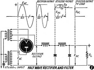
Fig. 1 - Half-wave rectifier and filter.
Eac - Transformer secondary voltage. f - Frequency
of supply voltage. fr - Ripple frequency. Edc - D.C.
voltage, average. Idc - D.C. current, average. R1 - load
resistance. Er - peak value, fundamental component of ripple voltage.
RF - ripple percentage. C - Capacity (farads).

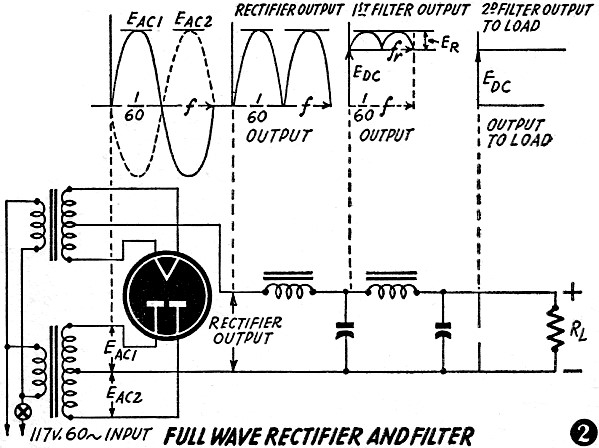
Fig. 2 - Full-wave rectifier and filter.
The complex problems of power supply design have in the past been considered
too difficult for the average experimenter and constructor. Mr. Dolan has presented
a simplified and very useful system of calculating constants of power supply
filters.
The direct current and voltage delivered by the rectifier of a power supply
includes an alternating current component. It is the duty of the filter section
to remove this alternating current component to a degree governed by the use
that the direct current is to be put to. This article will describe the commoner
filter systems and tell how to calculate a filter system for a given requirement.
The amount of filtering required for a specific purpose depends completely
on the amount of alternating current hum permissible in the circuit. A microphone
input channel will require excellent filtering because any hum present in this
stage will be amplified in succeeding stages. Generally the alternating current
component cannot exceed 0.005 of the direct current voltage for microphone input
circuits. An audio-frequency amplifier may tolerate between 0.01 and 0.1 or
more in the case of a class "B" stage. Some types of photoelectric equipment
may tolerate 10% or even more. Certain switching circuits may be operated with
no filter at all and still function reliably and accurately. In some cases a
simple resistance-capacitor filter will be fully adequate.
Figs. 1 and 2 show a typical half-wave rectifier power supply system and
a complete full-wave rectifier power supply. Above each diagram the functions
and wave forms and proper nomenclature is indicated at each point along the
filter system, the rectifier, and the transformer. By reference to these diagrams
we can pick out the various components of voltage, current and frequency which
arc tabulated beneath the diagrams. Because of the increasing impedance offered
to harmonics by the filter and as the harmonic content of the wave fed into
the filter is small, if the filter is designed to handle the fundamental component
of the ripple frequency it will suppress all harmonics, so the ripple due to
harmonics need not be considered.
The ripple frequency is a function of the supply voltage and the type of
rectification used. A half-wave rectifier delivers a ripple frequency equal
to the supply frequency. A full-wave or a bridge system of rectification delivers
a ripple frequency to the filter equal to twice the supply frequency.
The condenser input filter is of particular value in low-current circuits
because of the fact that for a low current drain the filter condenser can supply
the required voltage to the load during its discharging cycle. By the same token,
the voltage output of the condenser into a low-current load approaches the peak
value of the impressed voltage delivered by the rectifier tube or tubes.
This type of set-up is economical as far as trans former and rectifier costs
go, but requires twice the filtering of a full-wave rectifier system if the
same ripple voltage is to be attained in both cases. The effectiveness of the
voltage-gaining properties of the condenser input filter decrease with an increase
in the current drawn by the load. This means poor regulation. With a half-wave
rectifier the effect on the transformer is such as to reduce its efficiency
by saturating the core and secondary winding with direct current, making for
less efficient transformer operation. On the other hand, if the current drain
is small and a high voltage is needed, this type of filter and rectifier system
may be most economical and desirable. If a supply is desired for the high voltage
on a cathode ray oscillograph, this type of circuit will answer the purpose
in an excellent manner; the cost of parts is low, the circuit is compact, and
of most importance, the current drain is low and stable. Under these conditions
half-wave rectification and condenser input are not only possible but advisable.
Three types of rectifier systems are commonly in use for single-phase current
rectification, the half-wave, the full-wave, and the bridge rectifier. We may
construct a chart to show the characteristics of the various types of rectifier
systems and include the data required for filter circuit design. Such a chart
is given in Table 1.
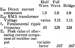
Table I - Characteristics of the various types of rectifier
systems and include the data required for filter circuit design.
The first and most important consideration is the amount of alternating current
component at the input of the filter. This is given in the above table and is
a consequence of the type of rectifier used. In the case of the half-wave system
it is also a consequence of the amount of current drawn and the type of filter
used. For the full-wave rectifier the value of the alternating component is
0.667 of the direct current component; and for the bridge rectifier circuit
it is also 0.667 of the direct current component of the rectified output wave
form.
There are three types of filter circuit to be considered in this discussion,
the first being a filter consisting of only a choke and condenser; the second
consisting of a two-section filter, two chokes and two condensers; the third,
the resistance filter.
In considering the first filter input condenser, there are two important
considerations; the smoothing effect, and the effect of the condenser on the
available voltage. The actual formulae and engineering calculations involved
in the calculation of the true effects of the input condenser are complicated
and involve consideration of the voltage source impedance, the resistance of
the rectifier tube, the input capacity, and the leakage reactance in an involved
relationship. A few simple graphs will illustrate the effects of this input
condenser in a manner which will be fully satisfactory for all practical uses.
Fig. 3 is a graph illustrating the variation of voltage for various load
currents and different values of capacity utilized as input condensers. We note
that increasing current will lower the voltage, thus causing poor regulation.
The wide space occupied by the curves further indicate the poor regulation as
also does the percentage voltage change for varying loads. The use of this chart
is self-explanatory and no difficulty is likely to be experienced by anyone
who understands radio fundamentals.
The graph in Fig. 4 indicates the ripple percentage resulting from various
values of capacity and load resistance. We note here that in all of these calculations
the effect of both capacity and load resistance and load current are very important
in their effects on ripple.
The graphs in figures 3 and 4 are both for 120-cyc1e ripple frequency as
would be the case for full-wave or bridge rectifiers. The use of condenser input
for half-wave systems is not recommended except under the conditions previously
noted. One effect of condenser input is to produce a higher peak voltage and
current on the rectifier tube or tubes than is imposed with the choke input
system. The ratio of peak to average plate tube current is higher.
The most important considerations involved in the calculation of filter output
voltage using condenser input are the source impedance, which consists of the
leakage reactance and resistance of the transformer, the tube resistance, and
the resistance of the load; the value of the condenser not being of prime importance.
The important considerations in reference to filtering ability and the reduction
of ripple voltage are the actual capacity and the load resistance. Later on
in this discussion an example of the calculation of a condenser input filter
shall be given and the means of using these charts and graphs will be readily
apparent.
We may now proceed to the choke input filter consisting of a choke followed
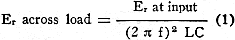
by a condenser as shown in Fig. 5. The formula for the determination of the
amount of ripple voltage that this type of filter will pass with various values
of L and C is:
As the ripple factor is what we are interested in we will work out the equation
for this factor. Let us assume a full wave or bridge rectifier, then Er
at the input to the filter will be 0.667 Edc and fr will
be 120 cycles. Substituting these values in this equation (1) we find our next
equation to be:
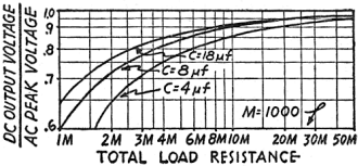
Fig. 3 - D.C. output vs. A.C. peak voltages.
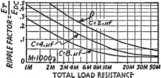
Fig. 4 - Ripple at filter input and output.
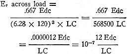
But, as the factor we desire is the ripple factor which is equal to Er
divided by Edc, we must divide this equation by Edc to
find the ripple factor. Doing this we have:
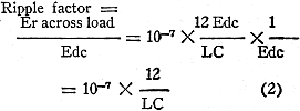
In use this formula should be used for full-wave or bridge rectification
only as the ripple frequency has been assumed to be 120 cycles and the peak
value of the alternating current component of the rectified direct current is
taken as being 0.667 of the direct current voltage. For half-wave calculating
the ripple frequency will be 60 cycles and the above equations can be worked
out with that value merely by substitution of 60 in place of 120 in the formula.
Value of the peak alternating current component will vary with the load drawn
but a figure of 0.7 can be used in calculations. For heavy loads and to allow
a margin of safety it would be better to use a higher figure. About 0.8 should
be fully satisfactory. It is difficult to give an exact figure, but for all
practical uses and purposes, those given above will prove fully satisfactory.
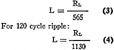
In all our choke-input filter designs it is supposed that the input inductance
is of sufficient size as to maintain a continuous flow of current through the
circuit under operating conditions. This is a function of the actual inductance,
the .resistance of the load, the alternating current component of the rectified
wave, and the direct current voltage output of the rectifier system. As the
last two mentioned figures represent a constant for any given type of rectification,
a simple formula will show the minimum amount of inductance required to satisfy
the conditions of maintaining current flow throughout the entire 360 electrical
degrees:
For 60 cycle ripple:
Unless these minimum amounts of inductance are used the formulas and graphs
given for choke input filter design cannot be used with accuracy. Imperfect
filtering and high peak tube currents will result from a deficiency of inductance,
with possible damage to the rectifier tubes. In the case of a varying load on
the rectifier and filter system the conditions of minimum inductance must be
observed at all times. To accomplish this it may be desirable to connect a bleeder
across the output of the filter in order to maintain a minimum amount of current
flow. Another method often used is to use a "swinging choke" in the input of
the filter. A swinging choke has a relatively high inductance for low current,
which drops with increasing current. By reference to the proper formula, which
will depend on the type of rectification, and by use of the maximum and minimum
inductance values, it is easy to select the proper choke so that flow will be
maintained for all values of current.
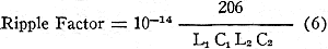
Our next consideration is the two-section filter shown in Fig. 1 or 2. In
this case, we have merely used two single sections, one following the other.
The amount of ripple voltage present at the output of this type of filter is
calculated from the following formula:
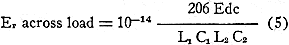
and to find the ripple factor we have:
In working with this formula it is best to have the product of the first
section of the filter approximately equal to the LC product ofthc second section.
The above formulas, numbers (5) and (6) are for use with 120-cycle ripple frequencies.
For 60-cycle ripple frequencies (as would be encountered with half wave rectification)
the numerator of both fractions would be changed from 206 to 34 and the fractional
multiplier changed from 10-14 to 10-12.
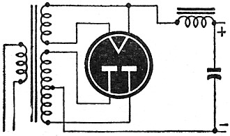
Fig. 5 - Power supply with choke-input filter.
Another method of effective filtering commonly used for low-current applications
is that in which resistors replace the chokes in the standard type of filter.
This type of filtering is advantageous because resistors are lower in cost than
inductances, thereby lowering the cost. The amount of filtering is a function
of the load resistance and the values of the filter components. An approximation
is given for the amount of filtering by the following formula:
This formula is for 60-cycle ripple frequency:
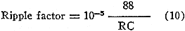
This second formula (8) is for 120-cycle ripple frequency as would be present
in full wave and bridge rectifiers. It must be remembered that the resistance
introduced into the circuit by the use of a resistor-capacitor filter will lower
the available voltage at the filter output. The voltage drop will increase with
increasing current. The above formulas are for a single-section filter consisting
of one resistor followed by one condenser.
Let us solve two problems: the first dealing with a single section choke
input filter; the second, a two-section filter with condenser input.
In our first problem we desire to secure a certain voltage to the load and
to find out what degree of filtering will result under the following conditions:
Given: Direct voltage to the load: 340 volts.
Rectification: Full wave, type 80 tube.
Current :125 milliamperes, load current.
Choke: 30 henrys, 160 ohms resistance.
Condenser: 4.0 Microfarads. Power input: 60-cycle.
We wish to find:
The transformer voltage each side of center
tap.
The ripple factor to the load.
The actual amount of alternating current voltage
at the load.
Our first consideration is the voltage drop in the choke. As the current
is 0.125 amperes and the resistance is 160 ohms, the voltage drop through the
choke is 20. The rectifier must therefore supply 360 volts to the filter input.
By consulting a tube manual we find the voltage drop, at 125 milliamperes, through
the type 80 tube to be 62 volts. The transformer must then supply 360 plus 62
volts or 412 volts. Multiplying this figure by the full-wave rectification factor
1.11 we find that the transformer must deliver 457 volts. A commercial transformer
would deliver 450 volts. By using a choke of lower resistance, about 100 ohms,
the voltage drop through the choke will be reduced with a subsequent raising
of the voltage to the load.
Using formula (3) we find the ripple factor:
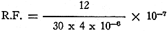
The foregoing expression is equivalent to :
12/120 X 10-1
And the ripple factor (R.F.) equals 0.01.
As this is equal to Er/Edc
and the direct current voltage is 340 volts then the actual ripple voltage,
Er is equal to 340 x 0.01 or 3.4 volts. It should be remembered that
"C" is in farads in all of these formulas. To convert to microfarads from farads
the microfarads must be multiplied by 10-6.
The second problem involves a two-section condenser-input filter. We wish
to find the ripple voltage and the ripple factor under the given conditions.
Given: Direct current to load: 400 volts.
Current: 200 milliamperes.
Full wave rectification.
Power input: 60 cycle.
Input condenser: 8.0 microfarads.
There are two filter condensers, each
4.0 microfarads.
There are two chokes, each 12 henrys,
80 ohms resistance.
To find: Transformer voltage each side of center tap.
Ripple voltage.
Ripple factor.
The problem must work from the load to the power input. The resistance of
the chokes is 160 ohms and the current is 0.2 ampere, therefore the voltage
drop through the filter is 32 volts and the voltage input to the first choke
of the filter from the condenser must be 4.32 volts. The input condenser is
working into an actual load of 2000 ohms load resistance plus the resistance
of the chokes, 160 ohms, or a total of 2160 ohms, total load resistance presented
at the input of the first choke of the filter. We now make use of the graphs
of figures 3 and 4 for our condenser calculations. Figure 3 is the graph of
load resistance, Edc and transformer peak voltage. This graph takes
into account the resistance and impedance of the transformer and the rectifier
tube or tubes and it is not necessary to add tube voltage drops, as the graph
incorporates this figure. The transformer voltage is given in terms of peak
voltage. Multiply by 0.707 to find the R.M.S. voltage. We know our load resistance
is 2160 ohms; finding the point representing this resistance and going up to
the proper capacity curve, then referring to the left-hand column we find that
the D.C. at the input condenser terminals under the given conditions is 0.73
of the peak AC. voltage, or:
432 equals 0.73 x A.C. peak voltage and A.C. peak voltage = 592 volts.
Converting to R.M.S. values:
AC. R.M.S. voltage = 0.707 A.C. peak and 0.707 x 592 = 419 volts.
The required A.C. R.M.S. voltage each side of the transformer center tap
will be 419 volts.
To find the ripple voltage we consult the graph of Fig. 4 .and, finding the
load resistance on the base line, go up to the proper capacity curve and read
off to the left side of the graph the ripple factor. In this case it is 0.13,
which means the actual Er at the condenser terminals is 0.13 x 432
or 56.2 volts. The formula for the calculation of the ripple factor of a two-section
choke input given at (7) is:
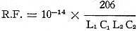
and substituting the given values:
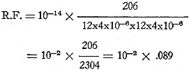
And R.F. = 0.00089 or 0.0009
The actual ripple voltage to the load is'
Er = 0.0009 x 400 or 0.36 volt
Thus we have found the required transformer voltage, the ripple factor, and
the actual ripple voltage.
These calculations are approximate due to the many variable factors involved,
such as the reactance and impedance of the voltage source, resistance of the
tube used, phase characteristics of the load, the resistance of the load and
the amount of current, as well as other factors involved.
Resistance-capacitance filters follow a similar line as the single section
choke filter. By study of our first problem and working along like lines but
using the proper formula, either (8) or (9), any resistance-capacitance filter
calculation can be made.
Posted February 2, 2021
|