|
January 1932 Radio-Craft
 [Table of Contents] [Table of Contents]
Wax nostalgic about and learn from the history of early electronics.
See articles from Radio-Craft,
published 1929 - 1953. All copyrights are hereby acknowledged.
|
This 1932 Radio-Craft
magazine article, in addition to reporting on early push-push power amplifier configurations,
demonstrates what a mess AC and DC power distribution systems were in the early
days of electric service. Standardization and regulation was at a minimum, and the
plethora of potential hazards to life and property makes you wonder how more people
were not killed, maimed, or had houses and businesses burned down. You hear a lot
about medical issues that came from lead-based paint on window sills, but the electrical
wiring and connected equipment were a mess. Back to the push-push amplifiers, though.
According to the author, the primary difference from the more familiar push-pull
amplifier is that the configuration removes bias from the unused half of the amplifier,
thereby improving efficiency. Both types use two cascode-connected Class B amplifiers
that when combined form a Class A amplifier.
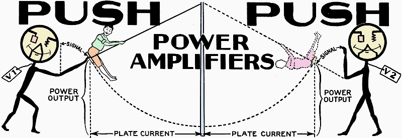
Push-Push Power Amplifiers
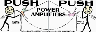 By C. H. W. Nason By C. H. W. Nason
Amazing Amplification
Power output six times greater! These few words portray the startling results
which may be obtained by connecting standard tubes in "push-push" and biasing the
grid circuit to plate-current cut-off as described by Mr. Nason.
Within a few months, many custom-built circuits will include the push-push amplifier.
There are two accepted methods for obtaining a large audio frequency power output
with low voltages.
The first involves the use of several tubes in parallel. Under these conditions
the power output obtained is that of a single tube, multiplied by the number of
tubes employed in the parallel arrangement - within certain limits governed by special
considerations of a highly technical character.
The second is termed the "push-pull amplifier" method due to the fact that the
circuit arrangements are such that both tubes are in action at all times, but with
their grid excitation "in phase opposition"; that is the plate-circuit signal voltages
are additive for currents of the same frequency as the input signal, but in phase
opposition for even harmonics generated in the individual tube circuits.
This fact results in a power output for two tubes in the push-pull connection
of about 2.4 times that obtained with a single tube because of the fact that the
tubes may be driven over a portion of the characteristic curve having a marked departure
from the linear before the distortion incurred becomes objectionable. Most receivers
of high fidelity employ push-pull output circuits.
Amplifier Classification
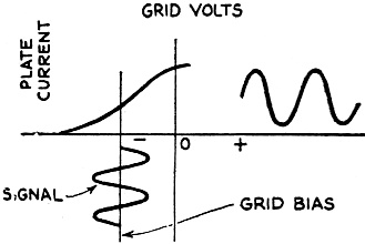
Fig. 1 - Graph of push-pull operation.
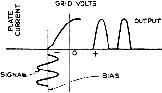
Fig. 2 - Push-push represented by graph.
The usual audio frequency amplifiers are termed Class "A". These amplifiers are
so biased as to operate over a substantially linear portion of their characteristic
curves and in such a manner that the output wave form is substantially that of the
input. Fig. 1 shows the grid voltage-plate current curve for a Class "A" amplifier.
It will be noted that the tube is given an initial bias such that the signal
varies the grid voltage about a point nearly midway of the linear portion of the
characteristic. The interests of high quality demand that the signal be limited
in such a manner that the grid is not driven positive during the positive signal
peaks and that operation is limited to the linear portion of the curve.
In the case of push-pull amplifier operation, it is permissible that the input
signal drive the tube slightly beyond the linear range, as the second-harmonic distortion
thus incurred cancels out in the plate circuit of the push-pull stage. In designing
push-pull amplifiers, the load impedance is chosen for the minimum third-harmonic
distortion inasmuch as the second-harmonic components will cancel out.
Class "B" amplifiers operate in the manner shown in Fig. 2. The operating
bias is so chosen that with no input signal the plate current is reduced to zero.
The bias required to achieve this end is obtained under certain conditions by dividing
the operating plate voltage by the amplification factor of the tube. Due to the
fact that the plate current has already been reduced to zero, it is obvious that
the tube will be inoperative during those portions of the signal wave driving the
grid still further negative. It is also readily seen that the output wave form will
represent only the positive half-cycles of the input signal. This fact is demonstrated
in the figure.
The Push-Push Amplifier
Some years ago, in a series of articles on the theory of low frequency amplifiers,
the writer made note of an amplifier especially designed for operation at low plate
voltages but with a relatively high power capability. This was the "Push-Push" arrangement
as originally developed by Alexanderson of the General Electric Company.
In a recent issue of the Proceedings of the I.R.E., L. E. Barton gives data on
the calculation of the power output obtainable with existing tubes under these conditions
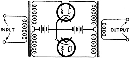
of operation. The "push-push" amplifier employs the push-pull connection, as shown
in Fig. 3. The operation of the circuit differs widely however, from that of
the push-pull circuit as the tubes are biased to cut-off of plate current and operate
as a Class "B" amplifier.
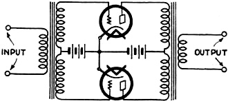
Fig. 3 - A "push-push" power amplifier. Divide Vp by mu
to obtain the tube's grid bias for plate current cut-off.
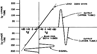
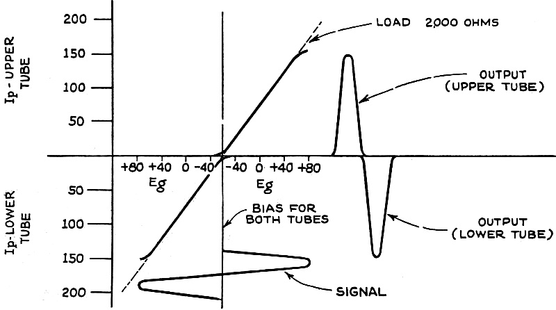
Fig. 4 - Alternate operation of two tubes connected for
performance as a "Class B" power amplifier is indicated in this graph. The schematic
circuit is Fig, 3. Note that operation is around zero grid potential.
The mode of operation is such, then, that each tube bears the burden of the power
transfer during a single half of the signal cycle. During the first half of the
cycle, the upper tube is being driven in the positive sense while the lower tube
is entirely inoperative. During the next half-cycle, the lower tube is being driven
in the positive direction while the plate current of the upper tube remains in a
quiescent state. The result is an amplifier stage in which a given pair of tubes
may be called upon to give an undistorted power output of from five to ten times
that obtainable with the same pair of tubes in Class "A" operation with the same
plate voltage!
The only changes demanded of the circuit are as follows: that the input transformer
be of low ratio, since the grid winding must be of low effective impedance during
the time that the individual tube is driven positive in order that the grid current
flowing will not disturb the constants of the circuit; that the input grid swing
or signal amplitude be several times that required for normal operation; that the
output transformer be capable of handling the heavy D.C. pulsations resulting; that
the power supply be capable of a high degree of regulation or constancy of voltage
under varying loads; and that the grid bias be obtained in such a manner that it
be not dependent for its value upon the plate current flowing through the tubes.
All these qualifications may be readily had with the equipment and apparatus
available on the open market.
The necessary regulation may be obtained. by the use of filter circuits of sufficient
capacity, or through the use of the D.C. power lines for plate supply. The arrangement
has a marked advantage for D.C. use, where the maximum potential available often
does not exceed 100 volts. For public address or theater amplifiers, the regular
220-volt supply (as obtainable from D.C. power circuits) is ideal, the resulting
power being far in excess of that obtainable with A.C. supply and a given pair of
tubes.
Operation of Push-Push Circuits
In Fig. 4 are illustrated the characteristics of the two power tubes in
"push-push" arrangement. The signal input is shown, as is the resulting output wave
form. The slight distortion resulting from the fact that the amplitude of the input
is such as to swing the alternate grids positive during a portion of each half-cycle,
does not exceed the 5% deemed permissible.
The curves given are for type '10 tubes with the load in each plate circuit equivalent
to 2000 ohms. For practical purposes, an output transformer devised for use with
a pair of '50's should serve. It will be noted that a dotted line has been drawn
in through the linear portions of the two characteristics; the point at which this
line cuts the base line gives the optimum biasing potential, and the point at which
the characteristic deviates markedly from the linear shows the maximum allowable
grid swing. In this case, the grid bias will be seen to be -60 volts, and the maximum
allowable grid swing about 120 volts (peak). This grid swing demand for power output
up to the maximum limit makes it necessary that we employ a push-pull stage employing
a pair of '27's (operated at their full plate voltage) prior to the push-push. stage.
The power output from the system is given directly from the formula:
P = Ip2 Rp
where Ip max. is the maximum plate current obtained during the positive peak
of each half-cycle (in this case about 170 ma.); and Rp is the load resistance (2000
ohms). Thus in this instance of push-push operation there is obtained a power output
of 29 watts, which may be compared with the power output obtainable with two '10's
in the more standard push-pull connection, with the same plate voltage, - or about
5 watts!
110 Volts, D.C., as "B"
Similar multiplications of the output "power available from a pair of standard
vacuum tubes operated at low voltages are available for service from the D.C. supply
- for example, from batteries, using the new "two-volt" tubes, etc. (Barton gives
the ratings for the type '30 tube as a Class "B" amplifier.) The '30 is the general
purpose tube - not the power output tube - of the battery-operated line, and its
use offers a simplification in filament circuit design over the design methods necessary
with the '31, which has a filament current of 130 ma. (as compared with 60 milliamperes
for the '30). The simplification is most apparent where the tube is used in series-connected
filament circuits, but also involves a saving of 0.140-ampere where parallel-wired
filaments are used - as with the air-cell battery. The normal output of a '30 is
16 milliwatts, while with two such tubes in "push-push" an output of 1 watt is obtained
- at a plate voltage of 157.5, and a negative bias of -16 volts.
The writer's original amplifier, prior to the publication of the Barton article,
employed two '45's with a plate voltage of 100 - as obtained from the D.C. power
circuit. The grids were biased close to the cut-off of plate current.
The high current drain necessary for the operation of these tubes resulted in
a tremendous light bill, nearly 200 watts being drawn from the supply circuit. The
output transformers on the market were not of low enough impedance for the optimum
conditions, but the power output obtained was fully equal to that with the same
tubes at their maximum rating. The grids were swung directly from a screen-grid
detector employing a '24 tube with a 1/4-megohm leak resistor and a 0.0001-mf. grid
condenser. Recently the system has been changed over to a pair of '12's, operating
from the full 220 volts.
It was found, upon investigating the fact that a blown fuse sent the full 220
volts through half of the apartment, that the 220-volt line came right up into the
kitchen instead of being split in the basement of the house. The receiver now draws
a load of 50 watts with the filaments in series and puts a maximum undistorted power
of about four watts into a dynamic reproducer working directly from a screen-grid
detector into the power tube grids. This involves a maximum peak grid swing of 40
volts on the power tube grids.
Despite the change to the smaller tubes, the power output obtained is still equivalent
to that obtainable from a pair of '45's working under optimum voltage conditions
- but the power drain is only about an eighth that which would be required were
the '45 filaments used and fed from the power line.
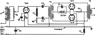
Fig. 5 - Schematic circuit of a complete "push-push" audio
amplifier which may be incorporated in any radio set operating on 110 volts D.C.
Of course, the primary of transformer T1 must be designed to match the output circuit
of the tube feeding the single '12A.
The circuit arrangement is shown here, Fig. 5, as adapted from the present
receiver, but with provision made only for its operation as a phonograph or public
address amplifier from the 220-volt lines. In almost all D.C. locations the 220-volt
supply is available; either immediately at hand, or so close that it requires no
great effort to tie in to it. The simplification of the amplifier as shown, over
a job employing '45's, is rather obvious - the business of dropping the filament
voltage along a resistance is of considerable difficulty when working with currents
of the magnitude involved when the '45 is employed; and it is not likely that any
job will be encountered where a greater power output than is available from the
unit shown in the figure will be demanded.
It must be repeated so that it will surely "sink in," that the output from the
twc '12's connected in "push-push" as shown in the diagram, is the equivalent of
that of a pair of '45's operated in push-pull at the maximum allowable plate voltage.
If necessary, the job shown can be made battery-operated with no sacrifice in power
output although it will be necessary to cart around a small six-volt storage battery
and a block of five 45-volt heavy-duty "B" batteries.
For the guidance of constructors, the following list of material used in the
writer's amplifier is given:
List of Parts
One volume control potentiometer, 1/2-meg., R1;
One bias resistor, 28 ohms, 2 watts, R2;
One bias resistor, 630 ohms 10 watts, R3;
One filter resistor, 5,000 ohms, 2 watts, R4;
One Amertran input transformer, Type 406-A, T1;
One Amertran push-pull input transformer, Type 151, T2;
One Amertran push-pull output transformer, Type 443, T3;
One Amertran coupling impedance, Type 103, L1;
One Amertran filter choke, Type 557-A, L2;
Two by-pass condensers, 2 mf. (each), 200 V., C1, C2;
One coupling condenser, 1/4-mf., 200 V., C3;
One electrolytic filter condenser, 32 mf., C4.
Two 50-watt tubes with 1000 volts on the plates can be called upon to deliver
about 200 watts of undistorted audio power output; or a pair of '10's (as indicated
in the curves ) can be operated from one of the mercury vapor '80's at a plate voltage
of 500 to give the same output power usually necessitating a pair of 50-watt tubes
with a plate voltage of 1500.
The next radio season will in all probability see the use of this power output
system in many radio receivers. The writer already knows of several manufacturers
contemplating the use of the arrangement in commercial receivers for direct current
operation.
Posted January 3, 2024
(updated from original
post on 10/1/2015)
|