|
May 1945 Radio-Craft
 [Table
of Contents] [Table
of Contents]
Wax nostalgic about and learn from the history of early electronics.
See articles from Radio-Craft,
published 1929 - 1953. All copyrights are hereby acknowledged.
|
This second part of the "Radar Principles"
article by British engineer and researcher
Dr. R.L. Smith-Rose provides a historical perspective of the very
beginnings of radar systems. It appeared in the May 1945 issue of Radio-Craft
magazine. Although alluded to by technical visionaries like Hugo Gernsback, George
Orwell, Jules Verne, H.G. Wells, et al, for use in target detection and ranging
(but rarely speed, oddly enough). According to Dr. Smith-Rose, the first use of
radio waves for detection and distance measurement was in atmospheric studies to
characterize the ionosphere, in a bistatic configuration. It is an interesting and
quick read, and you might even be introduced to the concept of a "squegging" (self-quenching) oscillator.
"Radar
Principles - Part I" appeared in the April 1945 edition of Radio-Craft.
Radar Principles - Part II
Part II - Historical Development of Radiolocation
By R. L. Smith-Rose, D.Sc., Ph.D., M.I.E.E., F.I.R.E. *

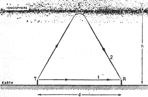
Fig. 7 - How height of ionosphere is checked.
The first applications of radio waves for determining the distance of a reflecting
surface were devoted to demonstrating the existence of the Heaviside layer as a
portion of the upper atmosphere, now known as the ionosphere, which is responsible
for the transmission of waves around the earth. After many years of speculation
with a variety of indirect experimental evidence, the first direct demonstration
of the existence of the ionosphere as a reflecting region was provided by Dr. (now
Sir Edward) Appleton and M. A. F. Barnett at the end of 1924 and during 1925.
With the cooperation of the British Broadcasting Corporation the wave length
of the Bournemouth broadcasting station was varied over the range 385 to 395 meters
over a period of from 10 to 30 seconds, and the strength of the resulting signals
at Oxford, about 100 miles distant, was measured. It was found that as the wave
length was varied, the received signal passed through a series of interference maxima
and minima, indicating that the signal was the result of two sets of waves arriving
by different paths; one set of waves was transmitted along the ground, while the
other arrived by an indirect path after reflection from a layer. After verifying
that the paths were in the same vertical plane, a measurement of the number of interference
fringes caused by a known change in wave length gave a measure of the height of
the reflecting layer in the region, which later became known as the ionosphere.
This was the first classical example of the use of frequency-modulated radio
waves for determining the existence and location of a reflecting layer which had
hitherto remained undetected by any direct experiment. We may therefore say that
the Heaviside layer was the first object to be detected by radiolocation experiments.
Shortly after the first of the above measurements were made, G. Breit and M.
A. Tuve began some tests in the United States of America, using interrupted continuous
waves which were the equivalent of pulses of continuous waves about 1 millisecond
in duration and with a recurrence frequency of 500 per second. At the receiving
station a high-speed oscillograph was used to record the incoming signals and permit
the examination of their wave-form. In July, 1925, experiments were made over a
distance of 7 miles using wave lengths of 71 and 42 metres, and it was observed
that the received pulses nominally of square wave-form, were distorted by the attachment
of humps, sometimes in duplicate.
These humps clearly indicated the arrival of a second wave-train, or echo, by
an indirect path; and from a measurement of its time retardation in relation to
the original hump due to the direct or ground wave, the path difference of the two
sets of waves could be determined. (See Fig. 7.)
In one of their publications, Breit and Tuve remark that their experiments on
the above lines arose out of some work being carried out at the time on another
method proposed by W. E. G. Swann and J G. Frayne. It is also of interest to remark
here that a United States patent was issued to H. Löwy on an application filed
in July, 1923, for a radio-frequency counterpart of Fizeau's method of determining
the distance of a reflector, to which reference has already been made. In this patent
Löwy describes an electronic switch used for alternately keying a transmitter
and receiver, so that the latter is only in a sensitive condition after the pulse
or train of waves has been emitted by the transmitter. It is not known whether this
device was put to any practical use.
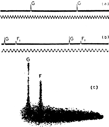
Fig. 8 (a) - Records of ground pulses and timing oscillations.
(b) - Same, with returned echoes. (c) - Same, photo of C-R screen pattern.
In the years following the dates mentioned above, a considerable amount of research
work was devoted to the development and use of methods of determining the height
of the reflecting layers of the ionosphere, using both the frequency-change and
pulse-modulation methods. A direct comparison of the two methods showed that they
gave substantially the same result in height determination; and in a paper published
in 1931, E. V. Appleton and G. Builder described certain important improvements
in sending and recording technique which demonstrated the advantages and illustrated
the possibilities of the pulse method, in so far as the signals arriving at the
receiver due to the ground wave and successive reflected echoes could be separately
received and recorded. At the sending station a tube oscillator arrangement was
used in the well-known "squegging" condition to produce trains of oscillations or
pulses of a duration of about 100 microseconds, spaced in time 0.02 second apart;
i.e., at a recurrence frequency of 50 per second. This type of oscillator had been
used previously to give a linear time base for cathode-ray oscillographic delineation
of waveform by E. V. Appleton, R. A. Watson Watt, and J. F. Herd, and its application
to ionospheric recording had been suggested by Appleton in 1928.
Since the time of transit of the waves to the E region of the ionosphere and
back again is of the order of 0.002 second, it is clear that using pulses of the
type just described, first the ground-wave pulse will be all over before the arrival
of the first echo, and secondly, that there is ample interval between successive
ground-wave pulses to receive and record one or more echoes. For visually observing,
and subsequently photographing, the nature of the received signals, a cathode-ray
oscillograph was used, with a time-base provided from a similar basic circuit using
a squegging oscillator, the stroke-frequency of the time-base being synchronized
with the pulse recurrence frequency of the sender, so that a stationary image on
the oscillograph screen was produced showing the ground wave and any echo waves
received.
The type of result obtained is shown in Fig. 8 (a), (b) and (c) which are
reproduced from the paper referred to above, and are specimens of the actual records
obtained by Appleton and Builder in 1931. Fig. 8 (a) shows the ground-wave
pulses received without echoes, while Fig. 8 (b) shows the presence of a single
echo signal after reflection from the F1 layer. In this case the time
interval can be measured in terms of the trace of an alternating current of frequency
1115 cycles per second shown below the signal record. Fig. 8 (c) is a snap
photogrgph of the echo pattern on the cathode-ray tube, showing the ground wave
G and the F region echo delineated on a time-base, which in this case corresponds
to a period of about 12 milliseconds. This was probably the first published picture
of what is seen on the screen of the cathode-ray tube of a sending and receiving
system used for determining range by measuring the time delay of the echo signal
relative to that of the ground or direct path signal.
The pulse-generating oscillator, and the cathode-ray tube and linear time-base
combination so described by Appleton and Builder in 1931, formed the basis of the
technique used some four years later in the first Radar experiments on aircraft
detection conducted in this country.
Aircraft Height Indicators
While scientific research on methods of exploring the ionosphere was being conducted
on the lines described above, a corresponding technique was being developed concurrently
and on very similar lines for the purpose of producing an instrument for indicating
the height of an aircraft in flight above the ground. For example, in 1928 J. O.
Bentley described a method in which frequency-modulated waves are radiated towards
the earth from a transmitter on the aircraft. A receiver, also on the aircraft,
receives the waves after reflection from the ground and combines them with those
received direct from the transmitter, the latter waves differing slightly in frequency
due to the time of travel of the waves to the ground and back again. The frequency
of the beats in the receiver resulting from the two sets of waves is thus a measure
of the height of the aircraft above the ground beneath, as distinct from its altitude
above sea-level, which is what is indicated by the type of altimeter dependent upon
barometric pressure.
This instrumental technique was later improved by L. Espenschied in 1930, and
culminated in a commercial pattern of "terrain clearance indicator" produced by
the Bell Telephone Laboratories in 1938. The apparent delay in the successful production
of this instrument was due to the fact that the heights in question are much smaller
than those involved in ionospheric research, and that therefore the echo-time intervals
to be measured are correspondingly less; e.g., 10 microseconds for about 5,000 ft.
An illustrated description of this method of echo sounding for aircraft was given
in Radio-Craft for January, 1939.
The pulse modulation method, of altitude determination in aircraft is clearly
applicable, provided that the pulse lengths are reduced sufficiently to discriminate
the echoes arriving at a much shorter time delay than is the case of the ionospheric
work. Such a system was, in fact, described by the Submarine Signal Company in June,
1933. Here the scheme proposed, for measuring distances used pulses of electric
waves, in association with a means of receiving the reflected echoes, and determining
the time interval between the emitted and received pulses with the aid of a cathode-ray
tube and synchronized time-base.
In December, 1931, the British Post Office observed the effects of reflection
of waves from aircraft in the course of some radio communication tests being conducted
on a wave length of 5 metres over a path 12 miles long. Extracts from the station
log show that on various occasions the received signal was subject to a beat type
of variation, which was not only audible but was detectable on the volume indicator
of the receiver. The amplitude of the beat varied from about ± 1/2 db. up to 10
db. on some occasions, and at all times when this occurred an aircraft was found
to be flying in the neighborhood at various distances up to 2 1/2, miles and at
heights up to 500 feet. The period of the beats varied from 5 to 15 per second;
and this is to be compared with the calculated value of 11 per second for an aircraft
flying directly towards the receiving aerial at a speed of 60 m.p.h.
This experience was confirmed by further observations made in America in 1932
by engineers of the Bell Telephone Laboratories in the course of an investigation
of the mode of propagation of radio waves in the range of wave lengths between 4.7
and 5.7 metres. In a paper describing this work by Messrs. C. R. Englund, A. B.
Crawford and W. W. Mumford, and published in March, 1933, it is stated that an aircraft
flying about 1,500 ft. overhead and approximately along the line joining transmitter
and receiver, a noticeable flutter of about four cycles per second was produced
in the low-frequency detector meter of the receiver. When observations were carried
out in the neighborhood of an airport, it was noticed that nearby aircraft produced
field strength variations up to 2 db. in amplitude. Similar re-radiation was noticed
at various subsequent times, occasionally when the aircraft was invisible.
It was thus clearly established, over ten years ago, that radio waves reflected
from aircraft in flight could be detected with suitable receiving equipment on the
ground; and it now remained to be seen whether this principle could be applied to
the development of a technique for the detection and location of aircraft at ranges
and under conditions of practical utility as an aid to navigation in peacetime and
as a defensive weapon in war. This important, and by no means easy, step was accomplished
by a small group of scientists working under the direction of Mr. (now Sir Robert)
Watson Watt, who was at the time Superintendent of the Radio Department of the National
Physical Laboratory, incorporating the Radio Research Station at Slough where the
initial experiments in the radio location of artificial objects in this country
were conducted.
Watson Watt, in association with the late J. F. Herd, had also devised the original
form of visual direction finder, using twin balanced amplifiers and a cathode-ray
indicator.
After some preliminary experiments, members of the staff under Watson Watt's
supervision established a new "ionospheric" exploring station on the East Coast
of England, at which were installed the, for those days, high-power pulse transmitters
made at Slough, together with suiitable receivers and appropriate aerial systems
and goniometers for determining the direction of arrival of the echo waves, both
in azimuth and elevation, scattered back to the receiver from the aircraft which
was illuminated, as it were, by the flood-lighting effect of the radiation from
the transmitter.
The members of that small band of scientists and techniccal assistants will well
remember the thrill of seeing for the first time a clear image on the cathode-ray
tube due to an aircraft which was so far away as to be invisible to the naked eye;
the distance of the pip along the base line gave the range of the aircraft while
its bearing and elevation were obtainable by turning the knobs of the goniometers.
Much hard work and not a little ingenuity were still required to convert the
technique from an experiment in the hands of scientists to a working system which
could be used and maintained by this miscellaneous type of personnel which was at
that time provided by the Service departments for this new "side-line" of radio
communication or signaling. It was not long, however, and well before war was declared,
before more than one Service station was in operation, and the plotting of the tracks
of various aircraft, some on their legitimate civil or military duties, and others
whose business was perhaps less innocent, was a matter of daily routine.
Work in Other Countries
An indication of the trend of thought and activities in other countries in the
years before the outbreak of the present war can be gained from a perusal of one
or two publications which are available. Reference has already been made to the
patent taken out in U.S.A. by H. Löwy; but the main development in America
seems to have taken place partly in the Service research institutions, and partly
at the Bell Telephone Laboratories. The latter organization, after developing the
aircraft altimeter, demonstrated the use of this instrument in a modified form to
the detection of ships over short distances. With regard to the Continent, it is
to be noted that the Telefunken Company filed a patent in 1935, disclosing an arrangement
similar to the frequency-change method used by Appleton, with the modification also
suggested by Appleton that, while the carrier frequency remained unaltered, the
frequency of the modulation was varied, while the number of interference fringes
was counted at the receiver. The American journal Electronics published in September,
1935, a two-page set of illustrations descriptive of the aircraft detection arrangements
alleged to be under development by the Telefunken Company. An interesting feature
of this pictorial display was the reference to the use of wave lengths in the band
5 to 15 cm. and of magnetron valves with permanent magnets developed specially for
wave lengths of about 10 cm. An alternative scheme was also described by the Telefunken
Company in 1937, which utilized two beams of transmitted waves to produce a stationary
interference pattern, the disturbance of which by an object moving across it was
detected at the receiver.
French and Italian Apparatus
In Italy, E. Montu described a twin rotating aerial arrangement for locating
aircraft in bearing and elevation, and the patent specification of this arrangement
was published in this country in December, 1936. About three years later U. Tiberio
published the first part of a comprehensive paper, discussing various aspects of
the radiolocation of ships and aircraft, in the Italian periodical Alta Frequenza:
the later parts of the paper were apparently withheld from publication after the
outbreak of the war. An interesting development in France was the fitting of the
steamship Normandie with an iceberg detector, which was described and illustrated
in Wireless World for June 26, 1936. This equipment comprised a transmitter and
receiver operating on a wave length of 16 cm. and mounted in the fore part of the
ship. The transmitting and receiving aerials were of the dipole type and mounted
in parabolic reflectors, 75 cm. in diameter and installed at a distance of 6 metres
apart; this arrangement provided a beam having a width of ± 10 deg. at half amplitude,
and the reflectors could be rotated automatically through an arc of 40 deg. When
the receiver indicated the arrival of a signal from the transmitter after reflection
from a distant object, the two parts of the equipment could be manually and accurately
trained on this object, the distance of which could then be calculated from the
directions of the transmitted and arriving waves. In this manner it was claimed
that a coastline could be located at a distance of 20 km., and large ships were
detected at ranges up to about 7 km.
Such was the state of affairs abroad as judged by the sparse published information
available. As to what was the actual state of affairs at the outbreak of the war
in Europe must remain a matter of speculation at the present time; but many readers
will look forward with interest to the time when more facts may be disclosed, and
the progress of the Radar technique con-ducted by the various belligerent nations
may be described and compared.
(The above article was reprinted by special permission of Wireless World, London,
England.)
Our Cover Feature "Japanese Radar"
 The Japanese
radar, which appears on our front cover this month, is a sequence from the Warner
Brothers' film Objective Burma. This elaborate radar installation was located
in the Northern part of Burma and a United States Task Force was charged with eliminating
it. In the movie this mission was successfully completed and the installation blown
up. The Japanese
radar, which appears on our front cover this month, is a sequence from the Warner
Brothers' film Objective Burma. This elaborate radar installation was located
in the Northern part of Burma and a United States Task Force was charged with eliminating
it. In the movie this mission was successfully completed and the installation blown
up.
This fanciful radar, cooked up by the Hollywood technicians, looks most impressive
in the motion picture and is supposed to let the public in on the sacrosanct wonders
of radar - still suppressed by the Allied military authorities.
This particular Japanese radar installation was manned by two operators
and was a revolving affair, the entire framework, transmitter, receiver, and operators
rotating continuously.
Spectacular as it appears in the motion picture, modern radar installations do
not look anything like this. Indeed, most modern installations are quite compact,
probably not too many of the cumbersome revolving types being in existence today.
Nevertheless, the radar principle of transmitting microwaves, which are then
reflected back to the operators, is correctly pictured for a not too technical public
consumption.
Needless to say, the Hollywood technicians could reasonably well have shown a
modern radar installation as it really appears, but in this they were prevented
by military censorship.
* National Physical Laboratory.
Posted December 30, 2021
(updated from original post on 8/22/2014)
|