|
July 1946 Radio-Craft
 [Table of Contents] [Table of Contents]
Wax nostalgic about and learn from the history of early electronics.
See articles from Radio-Craft,
published 1929 - 1953. All copyrights are hereby acknowledged.
|
During World War II, Germany
terrorized Europe with it rocket bombs, most notably the
V-1 Buzz Bomb and the
V-2 Rocket. The "V" prefix,
BTW, stands for Vergeltungswaffe, translated as "vengeance weapon," or "retribution
weapon." Both "vengeance" and "retribution" are really misnomers since it was Germany
that was the aggressor in both WWI and WWII. The vengeance or retribution in Hitler's
view was likely the punishment and restrictions imposed on Germany by the
Treaty of Versailles
for its vicious and inhumane behavior before and during World War I. History
shows they doubled down on it during World War II. But I digress. This 1946
article in Radio-Craft magazine proposes a scheme for a "radar rocket"
system that could detect, acquire, and intercept an enemy rocket bomb in flight
- a concept that was never really successful until the
Patriot Missile was
deployed in the 1990s as part of the
Strategic Defense
Initiative (SDI, aka "Star Wars"). This "Remote Control Weapons"
editorial appeared a year earlier in the August 1945 issue of Radio-Craft.
Radar Rockets - May Be the Answer to the Rocket Bomb
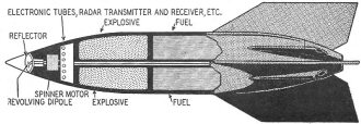
Fig. 1 - How a future radar defense rocket may look.
By H. W. Secor
One of the problems now engaging the attention of our military experts is to
provide a strong defensive weapon to combat flying rockets and bombs. In the next
war - should one occur - the enemy will loose a barrage of long-range rocket bombs
on our cities and vital industrial plants. Some of these will doubtless be atomic
bombs. High speed jet-propelled fighter planes may knock down some of them, but
some surer way of fighting such an attack is needed. Counter-attack rockets immediately
suggest themselves.

Barry Winfield Secor was born in Brooklyn. June 11, 1887. Studied
electrical engineering in Philadelphia and New York. Worked as electrical inspector
and power plant engineer 1910 to 1912. Has occupied many positions in the radio
technical and journalistic world, among them: assistant editor Modern Electrics,
1910 to 1912; engineering department; Western Electric Co., 1912 to 1914; managing
editor, Electrical Experimenter, 1914 to 1919 (engineer to Electro Importing Co.
during the same time, designing several arc generators, quenched spark sets and
amplifiers); managing editor, Science and Invention, 1919 to 1929. Lectured weekly
on radio and popular science subjects over Radio WRNY, New York, 1926 to 1929. Was
managing editor of Short Wave Craft, Avisation Mechanics, Televsion News, Radio &
Television, Model Craftman, etc.
During his long career in radio writing, Mr. Secor wrote a number of books, including
"How and Why of Radio Apparatus," "Induction Coil and Transformer Construction,"
"Simple Electricity Experiments" and was co-author with S. Gemsback and Austin Lescarboura
of the "Wireless Course in 20 Lessons" (used in teaching many radio students in
World War I).
Hobbies: Radio and Television set receiver construction; interpreting
scientific subjects for the non-engineering reader.
Microwave radars can be designed to direct the counter-attack rocket so that
it literally chases the enemy rocket and explodes as it nears the missile, thus
destroying it before it has a chance to reach its target.
Figure 1 shows a tentative plan for the positioning of the radar apparatus in
the rocket, also the disposition of the explosive and the control mechanism.
It may be objected that the tremendous speeds of rockets may not allow time for
such defense, but this is not the case. Even at a speed of 3,000 miles per hour,
a rocket launched from the (for rockets) close range of 500 miles would take a minimum
of ten minutes to reach its target. Actually the time taken would be much longer
because of the curved trajectory. Trans-Atlantic rockets would travel much more
than an hour.
The time allowed for launching the counter-attack rockets can be lengthened by
erecting radar outpost listening stations at such points as Iceland, Greenland,
Bermuda and other outlying places (also at similar Pacific stations) for spotting
the approach of enemy rocket bombs. (Fig. 2.) These stations would be continually
on watch. The information gathered by them would be relayed automatically to the
main base station on the mainland by radio, and counter-attack radarockets sent
out to apprehend the enemy missile and des-troy it before it reached within striking
distance of the mainland.
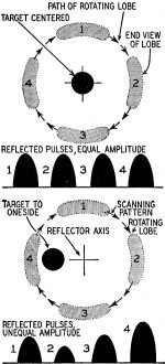
Fig. 6 - Conical scanning beam and its target.
Another plan is shown in Fig. 3 - an airborne long-range radar station. The flying
radar station would maintain radio contact with the ground bases for transmission
of target location data; an accurate location "fix" or position for the enemy rocket
can be supplied at any moment, or its course may be plotted continuously. The station
directing the radarocket can then combine the information received from two or more
of these spotters to plot the coming rocket's trajectory and aim a fighter rocket
in the proper direction to meet it. Electronic equipment could do all this automatically
and the release would be almost instantaneous.
The radarocket would ascend rapidly, using jet propulsion. Upon approaching the
target it could be detonated by the same means so successfully used in the thousands
of proximity fuze shells employed against the enemy in the war just ended. In this
device a radio wave was sent by the shell's miniature radio transmitter; reflected
radio waves picked up from the enemy target (such as a plane) by the receiving set
carried in the shell caused it to detonate when it came to within a distance of
about seventy feet of the target.
In another plan the course of oncoming enemy missiles is plotted by radar and
the launcher carefully aimed so the radarocket will intercept it. When this bloodhound
of the air comes within a reasonable distance of the enemy bomb or flying rocket,
it sends out a microwave which is reflected by the enemy missile (Fig. 4). These
reflected waves are picked up by a receiver carried by the radarocket and keep it
on the trail of the target.
This may sound far-fetched, but we have only to recall that some radars used
in World War II would track an airplane in flight and automatically aim antiaircraft
guns at it. These radars used conical scanning to achieve this feat.
The principle of conical scanning (Fig. 5) is that of using a reflector to concentrate
or beam a pulsed signal in a lobe pattern - and then cause the lobe to rotate around
the axis of the reflector,
A tiny dipole antenna is mounted off-center in the reflector and is rotated by
a small spinning motor. Only two successive positions (5-a) of the lobe are shown,
for the sake of clearness. Note (5-b) that the rotating radio lobe projected by
the dipole brackets the enemy target (a flying bomb for example).
Figure 6-a shows how the strength of the reflected echo signal from the target
varies for different positions of the lobe, when the target is off the center-line
of the reflector. When the target is on the reflector center-line (6-b) the strength
of each reflected signal is of equal amplitude. Thus the pulsed signal actually
scans the target.
The varying strength of the reflected signal actuates a correcting mechanism
(operating the vertical and horizontal rudders, or firing "course-correcting" auxiliary
jets on either side of the radarocket).
The revolving lobe describes a circular path (forming a cone as shown in Fig.
5-c). A target located on the reflector axis line gives a resultant echo signal
(on the receiver) having an identical amplitude for every position of the rotating
lobe. If the target is not on the center-line of the reflector axis, the echo signal
will vary in amplitude sinusoidally as the lobe is rotated. Whenever the lobe's
center (or axis-line) approaches the target there is an increased strength of reflected
signal. As the lobe rotates further, so that its axis or center line recedes from
the target focal line, a weaker signal results. The direction of the target from
the reflector axis is thus indicated by the relative phase of the variation or rise
and fall in strength of the received echo signal.
Fig. 7 shows two positions of the rotating lobe and the relative strengths of
signals reflected from the target in different positions. (See also Fig. 4).

Fig. 2 - Spotting the approach of enemy rocket bombs.

Fig. 3 - Airborne long-range radar station.
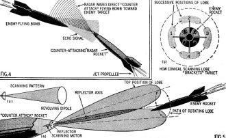
Figures 4 & 5 - Microwave which is reflected by the enemy
missile. Principle of conical scanning

Fig. 7 - Side view of conical scanning beam, showing response
for three positions to target.
The preponderant strength of signal received on the radarocket (when the target
is off to one side of the reflector axis) is caused to correct the course of the
rocket. With the conical scanning method (which was employed on the SCR-584 Radar)
applied to the flying bomb, it should hit the enemy target - once it comes within
range.
When reflected signals of varying strengths are picked up on the radarocket's
receiver (for a target off the centerline of the reflector axis) these signals are
integrated through suitable circuits fed into an amplidyne control amplifier and
finally impressed on an amplidyne generator (controller). The rotor of the generator
turns in accordance with the degree and polarity of the impressed current and relays
this position to a servo motor in the rear of the radarocket. This servo may operate
the vertical and horizontal rudders (or fire auxiliary course-correcting rockets).
The problem of identifying an enemy rocket poses a nice problem for the engineers.
By making careful observations of the relative speed and the course followed by
a rocket over a given period of time, it becomes possible to plot its probable course,
and be prepared to shoot it down long before it comes near enough to be dangerous.
Planes might also be used as carrier devices, bringing rockets to within a few
hundred miles and releasing them. However, if all friendly planes and rocket devices
are fitted with IFF (Identification, Friend or Foe - See Radio-Craft February, 1946)
any flying craft which did not give a satisfactory response would at once be classified
as enemy and counter-attack rockets sent out after it.
These precautions would be necessary only in peacetime (during periods when surprise
attack might be feared). In war, all friendly planes would be grounded, and whereabouts
and movements of friendly military planes definitely known. Thus any unknowns could
be classed definitely as enemy.
The idea for the radarocket was discussed with an expert who had considerable
experience with radar sets used by our fighter planes in hunting down enemy planes
at night or in foggy weather. It seemed from the results obtained with radar in
aerial warfare that the radarocket automatic direction control could be depended
upon to work up to distances of about a mile.
In radar reflections the area of the target which is to reflect the wave projected
against it has a great deal to do with the strength of the signal sent back to the
receiver. The larger the target the stronger the reflected signal. The reflecting
area of the enemy flying bomb would admittedly be rather small, but modern radar
has demonstrated almost unbelievable sensitivity; in some cases the tiny periscope
of an enemy submarine was a sufficient target to reflect the radar wave sent from
a scout plane several miles distant.
Posted October 11, 2021
|


