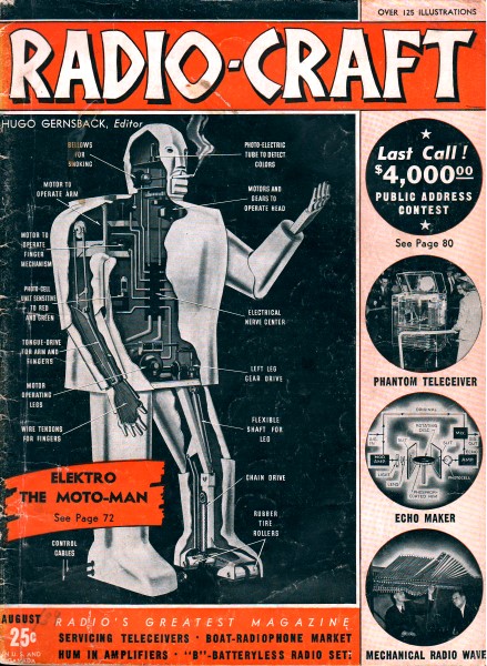
RCA Victor Model M-70 2-Unit Auto-Radio (Chassis No. RC-394)
|
|
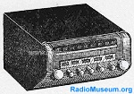
RCA Victor Model M-70 Auto-Radio (RadioMuseum.org image) This Radio Service Data Sheet is from the series published by Radio-Craft magazine in the 1920s and 1930s. The "2-Unit" part of the title indicated, per the schematic, that the power supply and the speaker output drivers were in a separate chassis that would have been mounted in the trunk or under a seat. I could not find an example of an actual RCA Model M-70 auto radio, but the thumbnail image to the left from information on the RadioMuseum.org website at least gives an idea as to its appearance. I am posting them for the benefit of people who restore those vintage models to working order. It is still possible to buy Sam's Photofacts packages that include schematics and alignment data, but these info sheets fill the gap for ones either not available, or for someone needing to get a feeling for what he/she is up against before making a full commitment to the task. RCA Victor Model M-70 2-Unit Auto-Radio (Chassis No. RC-394) Radio Service Data Sheet 
Mr. Serviceman: This is No. 259 in a series of Radio Service Data Sheets within Radio-Craft instituted with the October, 1929 issue. During this time the manner of presenting these Data Sheets has undergone considerable modification in accordance with comments by readers. Can you suggest any changes which will make these Data Sheets of greater value to the majority of the Servicemen who read Radio-Craft? Alignment Procedure Test Oscillator For all alignment operations, connect the low side of the test oscillator to the receiver chassis, and keep the output signal as low as possible to avoid A. V .C. action. Cathode-Ray Alignment is the preferable method. Connections for the oscilloscope are as follows: Vertical "H1" to terminal "C" on 2nd I-F transformer; vertical "0" to chassis. Output Meter Connect the output meter across the speaker voice-coil and turn the receiver volume control to maximum (fully clockwise) and the tone control to middle of range. Dial Calibration Rotate the gang condenser to its full-mesh (maximum-capacity) position and then adjust dial scale so that the pointer is aligned to the last calibration mark at the low-frequency end of the scale. Antenna Circuit It is very important that these instructions be followed when installing the M-70 receiver. The antenna circuit is designed to work with an antenna having a total capacity including the shielded lead-in not to exceed 150 mmf. If an antenna having a larger capacity is to be used, it will be necessary to add a condenser in series with the lead from the antenna filter L1 to the antenna coil terminal ("A"). Where a "Doublet Under the Running Board" type of antenna is to be used having a capacity of approximately 200 mmf., the condenser added should be approximately 500 mmf. The insulated running board type having an approx. capacity of 550 mmf. will require a condenser of approximately 150 mmf. Cars using an insulated steel top of approximately 3,500 mmf. will require a series condenser of 150 mmf.
Posted February 24, 2022 |
|