|
September 1947 Radio-Craft
 [Table of Contents] [Table of Contents]
Wax nostalgic about and learn from the history of early electronics.
See articles from Radio-Craft,
published 1929 - 1953. All copyrights are hereby acknowledged.
|
British engineer
John Sargrove was to the
production of radios what Henry Ford was to automobiles. At the time this "Robot
Makes Radios" article appeared in a 1947 issue of Radio-Craft magazine, Sargrove
had recently put his Electronic Circuit Making Equipment (ECME) fully automated
assembly line into operation. Applying knowledge from two decades of developing
methods of creating inductors, capacitors, resistors, and interconnecting conductors
using controlled deposition of various materials on flat substrates, he was able
to build 2-tube AC/DC radios at a rate of up to three per minute, with only two
ECME operators - one at the input and one at the output. The only manual assembly
required was the installation of a potentiometer-switch, a transformer, speaker,
and a power cord, plus joining the two fabricated
Bakelite plates together. You
will be amazed at what Mr. Sargrove's machine did. Unfortunately, raw material
shortages after a grueling war prevented further evolution and perfection of the
manufacturing process. His methods are clearly the genesis of many modern printed
/ deposited circuit techniques. In fact, a couple of the photos look like they could
be a micrograph of a semiconductor die.
Here is another article on the QSL.net website entitled, "
Modern radio pioneers: John Sargrove and Paul Eisler. The Automatic Radio Factory
and First Printed Circuits," by Pekka Ritamaki, OH3GDO.
Electronic component making equipment may revolutionize the manufacture
of receivers
By Major Ralph W. Hallows
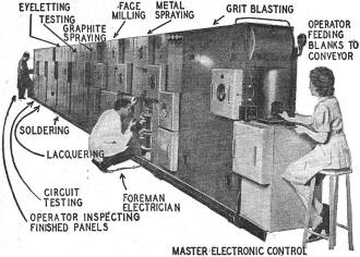
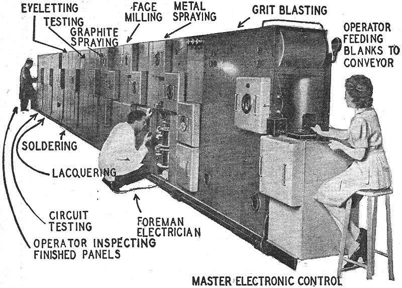
The 70-foot electronic circuit making equipment is automatic:
it requires only 2 operators.
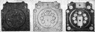
Fig. 2-a (left) - Molded blank: 2-b (center) after spraying:
2-c (right) after face-milling.

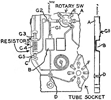
Figs. 3, 4 - Plan and section of part of panel.
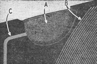
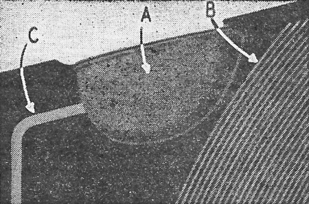
Fig. 5 - A, capacitor; B, coil; C, conductor.
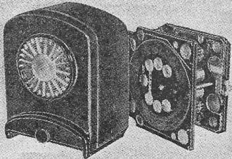
Fig. 6 - Complete 2-tube-and-rectifier radio.
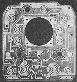
Fig. 7 - Corrugated discs are capacitor forms.
A new and entirely mechanical process for producing radio receivers at a rate
of 1 every 20 seconds has been developed and put into use by John Sargrove, Ltd.,
at Walton-on-Thames, near London, England. All components except tubes, large iron-cored
transformers, electrolytic capacitors, and loudspeakers are "grown" on a Bakelite
panel as it passes through a machine. The new process known as E.C.M.E., Electronic
Circuit Making Equipment, differs in many ways from systems using printed, deposited,
or sprayed conductors. The whole process is mechanical: One operator feeds Bakelite
blanks to a conveyor belt at the input end of the 70-foot long machine (Fig. 1)
and a second, at the output end, inspects the finished panels as they emerge. Every
stage of the manufacture is electronically controlled; each part of the machine
starts automatically when work comes in on a conveyor and stops automatically if
it has nothing to work on. Automatic cutouts operate if a fault of any kind develops
in any section.
The basis of the E.C.M.E. system is that an entire circuit is built on a pre-formed
Bakelite blank, which serves as the panel and as the dielectric of capacitors, the
formers of coils and the insulation between conducting paths. Fig. 2-a shows a typical
ebonite blank, with depressions
of various shapes and sizes molded into it. The straight grooves will eventually
become the conducting paths which take the place of wiring; a large spiral will
become a coil; the circular depressions, plates of fixed capacitors; the rectangular
depressions, the fixed plates of compression-type variable capacitors. Figs. 3,
4, and 5 indicate how this is accomplished. When depressions are molded opposite
each other on both sides of the plate, as at (B) in Figs. 3 and 4 and (A) in Fig.
5, a thin web of Bakelite is left between them. Metal-sprayed on both sides, this
web is made into the dielectric of a fixed capacitor. The straight grooves become
connecting paths; the spiral grooves become coils when metalized. The connectors
are made to cross by being placed on different sides of the panel. The connection
from the inner end of the coil is brought out on the opposite side of the panel,
(C) in Fig. 3. The connection is made with a metal eyelet passed through the panel
and clinched. A similar connection is seen at (D) in Figs. 3 and 4. Eyelets and
contacts of rotary switches, (E) in Fig. 3, and tube sockets (F) are inserted mechanically.
Resistors G1, G2, G3, G4, in Fig. 3 are made by spraying graphite into grooves of
suitable size and shape. Low-wattage resistors of high value occupy narrow zigzag
grooves. Wide grooves are used for high-wattage resistors. In practice resistors
from 1 ohm to 10 megohms are readily obtained. Lower values dissipate up to 20 watts.
The small portion of a panel in Fig. 3 contains resistors, capacitors, an inductor,
a rotary switch, and a tube socket. By the E.C.M.E. process each of these components
is "grown" simultaneously and automatically on the panel. The only manual operation
is inserting the switch.
The machine used in the process is built of a number of self-contained sections.
Different combinations of sections can be adapted for particular jobs. If a fault
develops in any section of the machine, electronically operated controls stop the
section affected and all sections preceding it. The following sections continue
to operate to minimize delays in production.
The blanks of Fig. 2-a are fed by the input operator to a conveyor belt. This
delivers them to the grit-blasting compartment which removes the outer skin of Bakelite.
A second conveyor takes them into the metal sprayer where they are under fire from
twin batteries of metal-spraying pistols, one battery dealing with each side. The
spraying pistols are of the wire-fed type, zinc wire being used. The entire surface
of both sides is covered with a thin film of deposited zinc (Fig. 2-b). If the panel
contains grooves for resistors, these will have been masked automatically during
the metal-spraying process. Face-milling takes place in the next section. This is
done by 2 batteries, each with 3 milling heads provided with diamond cutters. This
operation removes all of the deposited metal except that lying in the grooves and
depressions, and the panel now has the appearance seen in Fig. 2-c.
In the next operation, a set of automatically operated masks covers all of the
panel except the resistor grooves during the graphite-spraying process. These masks
are mounted on discs whose rotation is electronically controlled so that a clean
mask is always provided.
Tests are made automatically in the next section, and any faulty panels are rejected.
Eyeletting is done in the following stage; this includes the insertion of switch
and tube socket contacts. E.C.M.E. sets have no joints depending entirely on solder.
But solder is used to assure good connections at the few points where eyelets or
other through-panel contacts are clinched. The process is entirely automatic.
The final step in construction for this type of machine is the lacquer-spraying
of the panel, which covers the entire circuits with a protective layer. If tropicalization
is required, this is easily and effectively accomplished by using a coating of a
suitable plastic instead of lacquer. A final elaborate circuit test is made automatically
in the last section of the machine.
The panels emerge: still on edge, at the output end of the machine and topple
gently on to a horizontal conveyor, which takes them to the operators who perform
the few manual assembly tasks necessary. All prefabricated components, such as electrolytics,
large transformers, and loudspeakers, are designed so that they can be plugged in
and clinched in sockets provided by the machine. The only other piece of manual
assembly is to connect the various panels to each other. This is done by metal rods,
plugged in and clinched to form spacers and electrical connections between panels.
In the E.C.M.E. system, radio sets are built from numbers of small panels connected
in the way described. Apart from its convenience in the machine, the system has
other important advantages. The cost of individual panels is trifling. Should a
breakdown occur in a receiver, the serviceman, having tracked the fault to a particular
panel, simply fits in a replacement and throws the defective unit away. Fig. 6 shows
a 2-tube receiver made up of 2 panels and a cabinet.
Sargrove is limiting production to a simple 2-tube, plus rectifier, a.c.-d.c.
receiver. Materials are in such short supply in England that a new firm has little
hope of obtaining the necessary government permits unless it proposes to manufacture
something for which there is a ready export market. Undoubtedly there is a market,
notably in the Middle East and Far East, for a small receiver which can be produced
at a very low price. The simple 2-tube set with antenna coil and tickler does not
represent all that the system can produce. On the contrary, Sargrove and his assistants
are designing superheterodynes and television sets for manufacture by E.C.M.E. methods
as soon as the supply problem becomes easier.
By this time the reader no doubt will have a number of queries. Inductors, for
example. Can coils of reasonably good Q be produced? High-Q coils would be out of
place in a small regenerative receiver; but with the simple methods employed a Q
of 70 is readily obtained. Very much higher Q's have been produced in special ways,
which I am not at liberty to describe. Can sufficient inductance be obtained in
sprayed-on coils for them to form the primaries and secondaries of i.f. transformers?
One of the most promising methods is to use an iron-dust filler for the panel in
appropriate areas. What about tuning? Can it be made fine and sharp? It is hardly
that in the present small model, which has 3 preset positions on the broadcast band.
But new types of tuning with good performance and which lend them-selves to E.C.M.E.
production methods are being developed. The larger receivers of the future will
probably have a form of permeability tuning.
Next, capacitors. What kind of capacitance values can be obtained from sprayed-on
types? Fig. 7 shows a most successful method of obtaining capacitance values up
to 0.0005 μf by corrugating the webs in the blank. There are 2 methods of obtaining
higher values without completely sacrificing mechanical methods of manufacture.
One is to build a capacitor (the rest of the panel being masked) by alternate spraying's
of metal and of material of high dielectric coefficient. The second method is to
use a subpanel of material with a high dielectric coefficient. By either method
capacitances up to 0.03 μf are obtainable. If larger capacitors are needed, they
are plugged in and clinched in the way already described.
E.C.M.E. may play an important part in the manufacture not only of radios but
of many other kinds of light electrical equipment. You don't have to do much thinking
to realize how many fields may be open to it. In radio manufacture some of its biggest
advantages are the following:
(1) A plate containing 20 sprayed-on components is no more expensive to make
than one containing 10 or 12. An additional component of this kind, in fact, adds
nothing whatever to the cost. There is no need for a designer to cut down components,
such as capacitors, resistors, or chokes in order to keep within production cost
limits.
(2) No wiring mistakes can be made by tired or careless operators. There can
be no variations, large or small, in the length or positioning of conductors, since
the human element is eliminated.
(3) Radio sets can be manufactured more rapidly and far more cheaply than when
prefabricated components are assembled on a chassis and wiring is done by hand.
(4) A very small labor force is required. Each E.C.M.E. machine needs only 2
semiskilled operatives. A foreman-electrician can supervise several machines. Manual
assembly consists merely in plugging in the larger components.
(5) The ordinary radio may contain hundreds of soldered joints, each one a potential
source of trouble. In the E.C.M.E. set there are very few joints, the great majority
of conductors being integral with the components to or from which they lead. The
few soldered joints are clinched as well.
(6) E.C.M.E. equipment is lighter, more rugged, and more compact than that containing
wired connections and prefabricated components such as resistors and capacitors.
(
(7) Since the bulk of the components used are made simultaneously and automatically
in the machine, very few need be bought or made separately. Alterations in design
can be made without having to scrap large stocks of expensive components.
This revolutionary new method of radio assembly is the first serious and successful
attempt by Sargrove to produce radio apparatus by a completely mechanical process
and it well may be adopted ultimately by all manufacturers for mass production.
Posted May 16, 2024
(updated from original post
on 7/7/2018)
|