|
October 1930 Radio-Craft
 [Table
of Contents] [Table
of Contents]
Wax nostalgic about and learn from the history of early electronics.
See articles from Radio-Craft,
published 1929 - 1953. All copyrights are hereby acknowledged.
|
If you are from a family of electronics
hobbyists and/or professionals, then there is a good chance your grandfather and
possibly even your father kept a handy-dandy list of common circuit design formulas
handy. The list here Part 2 includes all the formulas on this page, which dealt
primarily with vacuum tubes, the schematics for which were presented in
Part 1 of the series. There was not an "app
for that" back in those days. Prior to a smartphone in every pocket, notes were
pinned to a lab wall or kept in a hand-written notebook.
Simple Mathematics for the Service Man
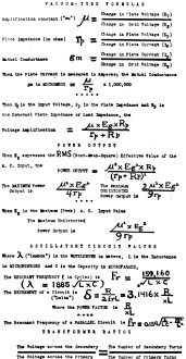
A chart of formulas which may come in handy at any time.
(Part II)
By Boris S. Naimark
The amplification constant of a tube - written as μ and pronounced "mu" - may
be defined as the ratio of the change in plate voltage, which is necessary to produce
a certain change in the plate current, to the change in grid voltage which will
produce the same change in the plate current. Structurally, the "mu" of a tube depends
upon the mesh of the grid and upon the spacing between the grid and plate. Electrically
it denotes the maximum theoretical voltage amplification possible or available within
the tube.
The plate impedance or plate resistance of a tube may be defined as the ratio
of change in the plate voltage to the change in plate current, and is expressed
in ohms. In tube charts the specified values of plate impedance are the A.C. values;
the D.C. values of plate resistance are equal to twice the value of the A.C. plate
resistance.
Mutual conductance - indicated as Gm - may be defined as the ratio of the change
in plate current to the change in grid voltage, and is ordinarily expressed in micromhos.
By the external impedance of a tube is meant the impedance of the coupling unit
or device which is connected between the plate and the filament of the tube. Considerations
of external impedance are of paramount importance; since the relation between the
value of a tube's plate impedance, and the impedance of its external plate-to-filament
circuit, governs the power output as well as the voltage amplification obtainable
from a given tube or tubes. In this connection, it is of interest that the plate
impedance of two tubes connected in parallel is just half of the plate impedance
of one of the individual tubes; while the plate impedance of two tubes connected
in push-pull is equal to twice the impedance of one of the tubes. (The above is
true only when two identical tubes are used.) It can be shown that the full value
of the "mu" of a tube can be obtained only when the value of the external impedance
is infinite.
Power Output
In practice, ninety per cent. of the "mu" of a tube is available when the external
impedance is between five and ten times as great as the tube's plate impedance.
The maximum undistorted power output of a tube is available only when the value
of the external impedance is equal to twice the tube plate impedance.
In addition to the "mu," and the external and internal plate impedances of a
tube, the power output depends upon the value of the signal input voltage. Doubling
the value of the signal input voltage doubles the voltage output of a tube; but
it quadruples the tube power output. In other words, voltage amplification is directly
proportional to the signal input voltage; whereas the power output of a tube is
directly proportional to the square of the signal input voltage. It should be understood
that power tubes supply the full rated maximum undistorted power output only when
operated at or near the specified maximum safe plate voltages and when the input
peak signal voltage is equal to the recommended grid bias.
A study of tubes discloses the fact that tubes having comparatively high values
of "mu," and therefore high values of plate impedance, are most suitable for voltage
amplification. Tubes having low values of "mu," and correspondingly low values of
plate impedance, show better power handling capacity, and are more suitable for
the output, or power stage of a radio receiver.
A study of circuit formulas is beyond the scope of this article; though we present
some of them in our chart, those who would learn the significance of them are referred
to any standard text on radio.
Posted September 28, 2022
(updated from original post
on 9/8/2015)
|


