Six-Inch Radio Waves
|
|
2.1 GHz (5.6-inch, or 14 cm wavelength) radio waves were an almost totally unexplored realm in 1930, with it and higher frequencies being the domain of theoretical research laboratories. Signal generators capable of producing much more than a few hundred megahertz were rare even in commercial applications. As reported here, centimeter−length electromagnetic waves were "according to the theories of Barkhausen and Kurz, [the] result of purely electronic vibrations, whose frequency was determined only by the operative data of the tube and was not dependent on any internal or external oscillation circuit." A half-wave receiving antenna picked up the transmitted signal with a simple diode detector to enable, after a couple stages of amplification, an audible signal. These are some of the earliest experiments at radio frequencies (RF) with parabolic metallic reflectors and polarization with a diffraction grid that could be rotated to set the polarization direction. Six-Inch Radio Waves
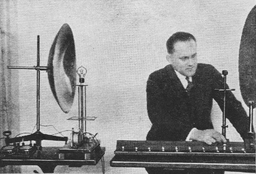
Fig. 1 - The tube is emitting ultra-short waves which are reflected, just like light, through the lens in the center, to a glass of water, and thence to the little receiver. They are produced by a "tuned-tube" and picked up by a crystal detector. Parabolic mirrors are used. Experiments are described. By Ernst Gerhard - Erlangen, Germany At a meeting of the German "Heinrich Hertz-Gesellschaft" (Heinrich Hertz Society), which took place a short time ago, Dr. K. Kohl, of the University of Erlangen, showed some very interesting experiments with undamped "monochromatic" waves 14 centimeters in length. The well-known Hertz experiments were presented with the aid of a modern auxiliary, the electron tube, together with many newer experiments. Some years ago Barkhausen and Kurz, while making investigations of the vacuum in electron tubes, discovered the presence of ultra-short waves of less than one meter wavelength. It appeared that, to produce these vibrations, the grid of the tube must be given a high positive voltage and the anode (plate) a relatively slight negative voltage. According to the theories of Barkhausen and Kurz, it was the result of purely electronic vibrations, whose frequency was determined only by the operative data of the tube and was not dependent on any internal or external oscillation circuit. Dr. Kohl, however, was able to demonstrate by new researches that, to excite these oscillations, there "must always be present an oscillatory circuit to determine the frequency. Especially by proper reduction of the elements determining the frequency, Kohl was successful, under normal operating conditions, in producing undamped waves with a fundamental length as short as 8 centimeters (3.2 inches) and to demonstrate their radiation into free space!
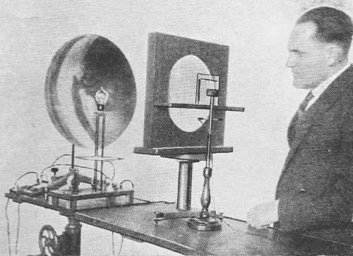
Fig. 2 - Here the radio waves focused by the mirror are reflected by the metal disc at the right. The result is an interference pattern of R.F. signal voltages.
Fig. 3 - The experiment of Fig. 2 is shown here schematically. The metal of the mirror and the screen reflects the 14-cm. waves sharply.
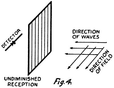
Fig. 4 - When this frame of parallel wires, at right angles to the wave front, is per perpendicular to the electric field, it allows the wave, to pass freely.
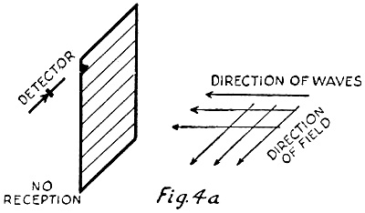
Fig. 4a - If, on the other hand, the wires of the Hertz "polarization grid" are turned until they parallel the electric field, they shield against it. In the experiments described below, the transmitter was a tube constructed by the firm of Tekade (Nuremberg, Germany) according to Dr. Kohl's directions, and containing in the glass bulb as the oscillatory clement a small spiral grid, which is excited at its natural frequency and radiates a constant wave 14 centimeters (5.6 inches) in length. A specially-made receiver, in the form of a rod half as long as the wavelength, was used; the detecting element (crystal) being set in the middle. (See Fig. 5.) The oscillation was modulated at audio frequency in the transmitter by a special process; so that the reception could be heard in the loud speaker, after two stages of audio-frequency amplification. Radiation Effects The experiments described below correspond to well-known experiments with "monochromatic" (single-wavelength) light. The practical demonstration of such optical experiments becomes possible if the wavelength of the electric waves is comparable with the linear dimensions of the experimental apparatus. With a 14−centimeter wavelength this requirement is completely satisfied. First, presence of free radiation was proved directly with the detector in the vicinity of the sending tube. It was shown that the radiation was polarized in a plane and in this case, the direction of the electric field was horizontal. If the axis of the receiver rod was turned until it was horizontal and parallel to the grid spiral of the transmitting tube, the sound received was a maximum. Turning the detector 90 degrees, in a horizontal or vertical plane, caused almost complete disappearance of reception. The influence of a straight "resonator" on the transmitter or receiver was shown by the following experiment: A small copper rod half as long as the wavelength (i.e., 7 centimeters - 2.8 inches) was placed behind the transmitter and parallel to the electric field, about a wavelength away. The rod was itself at the same time excited to its natural oscillations at the same frequency, and thus became a secondary radiator. In this way the intensity of reception could be noticeably increased. A similar experiment could be demonstrated at the receiving side. To produce a directed radiation there was placed behind the tube a parabolic mirror about 50 centimeters (19.7 inches) across, the tube being located at the focus of the mirror. In this way it was possible to produce an almost parallel "pencil" of rays. If a metal screen was placed in this, in such a way that the pencil fell diagonally on the screen, the rays were reflected in accordance with the laws of optical reflection. Their course could be followed exactly at the same time with the detector. (See Fig. 3.) The phenomena of diffraction, which are well-known in optics, could also be demonstrated with this radiation of waves. A round metal disc, 50 centimeters in diameter, was placed in the path of the rays. If the receiver was placed close behind this screen, no reception could be obtained; that is, the receiver was completely in the "electrical shadow" of the screen. At a distance of about a meter (39.37 inches) from the metal screen, however, the wave could be received again; that is to say, the waves curved around the edge of the screen. By moving the receiver still further away, it was possible to find in turn "maxima" and "minima"! This phenomenon corresponds to the well-known Arago experiment in optics; which shows the bending of visible light around the edge of a circular disc. The refraction of the wave-radiation was demonstrated by letting the parallel pencil of rays from the transmitter fall on a glass lens bout 30 centimeters (a foot) in diameter. By using the detector behind the lens, it was possible to demonstrate clearly the course of the radiation and in particular the place of greatest intensity, the focus of the lens. Absorption of Waves by a Conductor With this arrangement, the absorption of the waves by various substances was very beautifully shown. If a sheet of cardboard, hard rubber, dry wood, or a glass vessel of paraffin oil, was placed between the lens and the detector, there was no weakening of the reception. But, if a glass vessel of distilled water was placed in the path of the rays, the radiation was almost completely absorbed. Fig. 1 shows this experiment: the rays emitted by the tube are made parallel by the parabolic mirror. The parallel rays strike the glass lens and are concentrated by this into a focus; the detector is set up at this point. The glass vessel, between the lens and the detector, contains the liquid which is to be tested as to its absorption.
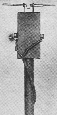
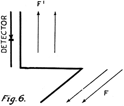
Fig. 5 - A close-up of the antenna and detector of the 14-cm. radio receiver. One of the most interesting experiments is the production of vertical electric waves. For this purpose the parallel rays are reflected perpendicularly from the concave mirror upon a metal screen, as shown in Fig. 2. The parallel rays strike perpendicularly on the circular metal disk and are thereby reflected. The approaching wave and the reflected wave coincide, between the concave mirror and the metal disc, and cause a vertical wave. If the detector is at one of the places marked with white in the illustration, the maximum strength of reception is secured. Between these places one gets tone minima. These maxima and minima correspond to the crests and nodes of the vertical wave. Polarization Effects The distinctive polarization of the waves was shown by means of the Hertz polarization grid. (See Fig. 4 and 4a.) This grid consists of a row of parallel copper wires, stretched 1 centimeter (0.4-inch) apart on a wooden frame 40 centimeters (16 inches) square. When this grid was placed in the path of radiation between the transmitter and the detector, with the grid wires perpendicular to the electric field, there was no influence on the reception. But when the frame was revolved 90 degrees, so that the wires lay parallel to the electric field, the radiation was almost entirely shut off. A further interesting experiment was the rotation of the plane of polarization. For this there was used a wire shape made up of three copper rods at right angles to each other, each 7 centimeters long (that is, half the wavelength). If the axis of the receiver rod was placed perpendicular to the electric field f there was no longer any reception. But, if the wire shape was placed before the receiving rod in such a way that one of the end-wires was parallel to the rod, reception could be clearly heard. In this case, in fact, the first length of wire lay parallel to the movement of the electric field and thus, by coupling, conveyed the primary oscillations into a direction perpendicular to the primary field; so that there resulted a secondary electric field f1 in this direction. (See Fig. 6.) This may be regarded as a model experiment for the rotation of the plane of polarization by the flow of electrons. A Tube Receives Its Own Waves By two experiments, for the conclusion, there was shown the possibility of tube-reception. For this purpose, the radiation sent from the tube was reflected back upon the tube. In one case the metal screen above described was used to do this; in the second case a small linear resonator, 7 centimeters long, was sufficient. It was shown that, according to the position of the resonator (i.e., the phase of the reflected radiation) the plate current of the tube can be modified. This experiment proves the possibility of reception of a wave by the very tube which sends it out and, at the same time, constitutes an actual, visible indicator of the operation of the tube.
Fig. 6. - The heavy line indicates the short coupling rod, which would pick up a signal in one of its sections; and, by the flow of current, transfer the signal to the detector. Lately, Dr. Kohl and his co-workers have even succeeded in making directional telephone experiments over an experimental distance of about 1,500 meters. The tubes used for receiving and transmitting in these experiments were absolutely alike; so that there was a possibility of using them alternately for the purposes of conversation. There is a great field of possibilities for the use of these short waves. Thus, in the technique of communication, they will be serviceable wherever the communication is to take place within the range of vision, but, above all, in cases where definite directional radiation is desirable for signal purposes (e.g., for coastal shipping and aviation). In medicine there seem to be great possibilities of their use in ultra-short-wave diathermy (i.e., the application of internal heat by short waves). Very recently an intensive investigation has been made of the physiological effect of short waves, about three meters in length, which has led already to surprising results at this frequency. Possibly shorter waves will prove still more effective. It should be recalled that an absorption maximum of water is found just at the frequency of the 14-centimeter wave. Finally, let us call attention to the possibility of the spectroscopic investigation of matter with these four-inch spectral lines. Along this line we may expect probably many discoveries regarding the inner structure of matter.
Posted August 1, 2023 |
|