Television and FM Antennas
|
|
This article on the design and use of antennas for television and FM radio was printed in a 1948 issue of Radio-Craft magazine. Equations and charts are provided for calculating element lengths for half-wave antennas, including directors and reflectors. Many types of antennas - dipole, stacked dipole, folded dipole, conical, adjustable "V," cross-element - are discussed regarding siting issues (location and height above the ground), and radiation patterns. It is a pretty good primer for someone new to antennas, and makes a great supplement to the data furnished in study guides for obtaining a Ham radio license. Television and FM Antennas
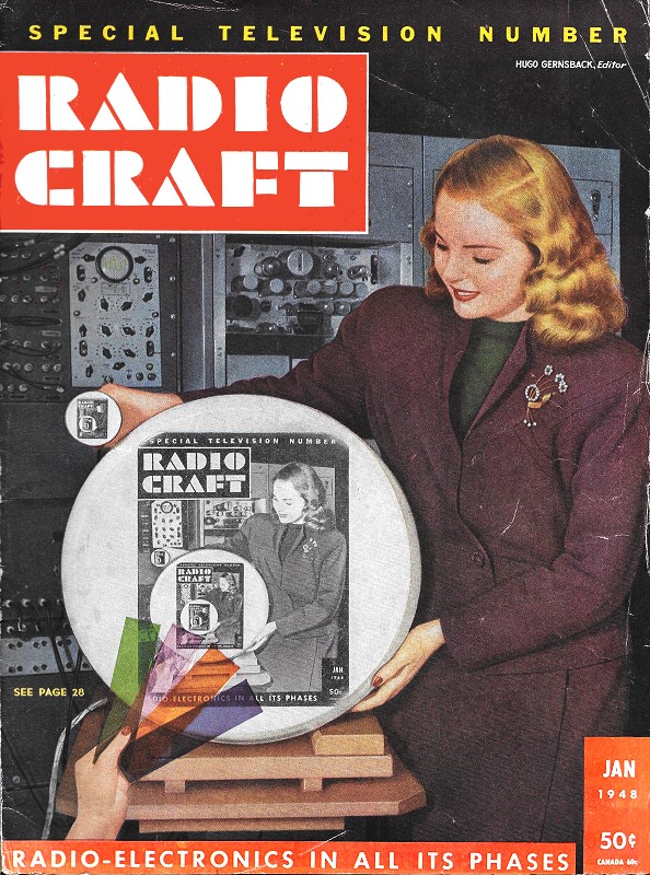
Fig. 1 - The dipole, simplest and basic antenna.
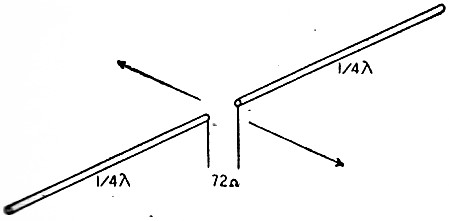
Fig. 2 - The correct length of FM and television antennas can be calculated from this chart.
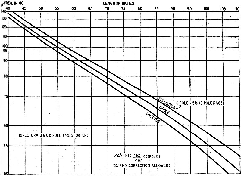
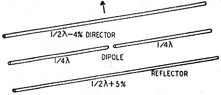
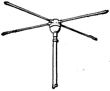
Fig. 3 - Directional reflector-director-dipole. By H. Winfield Secor Reception of television and FM signals calls for special antennas capable of intercepting high-frequency waves with maximum efficiency over a broad frequency band. Most antennas designed for this service are based on the simple dipole of Fig. 1. The combined length of the 2 rods (or tubes) is equal to 1/2 the wave length, minus a correction (about 6% for high frequencies) to compensate for the so-called end effect. (The electrostatic capacitance at the ends of a half-wave dipole, and also the fact that the velocity of the wave or current is slowed down in traversing a conductor, requires the dipole to be slightly shorter than the electrical wave length in space.) The formula for computing the length of the half-wave dipole is: L (in feet) = 462/f, where f is the frequency in megacycles to which the antenna is to tune. F is ordinarily the geometric center of the band to be received: 97.6 mc for the 88-108-mc FM band; 62.2 mc for the center of the lower television band; 195 mc for the center of the upper television band. (The geometric center of a band is found by taking the square root of the product of the frequencies at the extremities of the band. Thus for the FM band it is equal to √(88 x 108), or 97.6 mc.) Sometimes an antenna is cut to the frequency of the weakest station to be received, instead of to the center of the band.
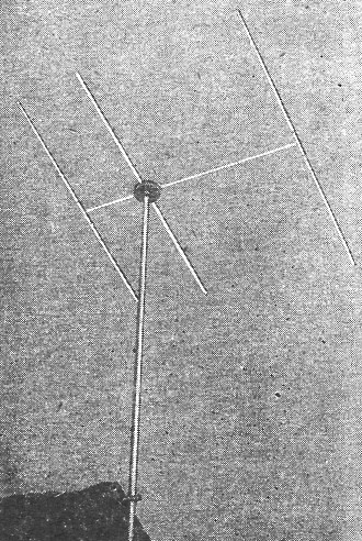
Fig. 4 - A commercial type 3-element antenna. The lengths of dipoles, reflectors, and directors for various frequencies is given in megacycles in the chart of Fig. 2. To calculate the dimensions of an antenna for the center of the FM band (call it 98 mc) for example we read across from 98 mc on the left-hand side of the chart until the horizontal line strikes the curve, marked dipole, then look down to length in inches. There we find 56.7 inches for the length of the dipole (both legs), or 28 3/8 inches for each leg. The length of the reflector, if wanted, is found to be 59.4, and the director length 54.4 or roughly 59 1/2 and 54 1/2 inches, respectively. The impedance of a simple dipole is approximately 72 ohms. It may be matched by a 50- to 100-ohm transmission line. Fig. 3 shows how a reflector or director can be added to the dipole to increase the gain in a forward direction. Maximum gain direction is indicated by the arrow. For television reception the reflector is usually spaced 1/4 wave length behind the dipole, to give broader tuning. The reflector is made 1.05 times the length of the dipole. The director element provides still greater gain in a forward direction. It is made 0.96 times the length of the dipole. Adding these elements makes the antenna response curve much sharper. The off-resonance response falls off quite rapidly. Fig. 4 is an interesting example of a dipole with director and reflector.
Fig. 5 - Folded dipoles are becoming popular.
Fig. 6 - Double dipole is sharply directional.
Fig. 7 - The cone is a basic wide-band antenna.
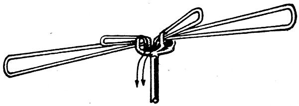
Fig. 8 - The cross, an antenna type used where non-directional reception is desired. The folded dipole at Fig. 5 provides a broader frequency response than a simple dipole, and is being widely used for both FM and television reception. It has an impedance of about 300 ohms, and is easily matched by a 300-ohm line. Most television and FM receivers have an input impedance of 300, ohms, so the match is good. The vertical distance between the top and bottom elements of the folded dipole is made less than 1/8 wave length, and averages 3 to 4 inches. To improve the gain in a forward direction, a reflector is often placed 1/4 wave length to the rear of it. The surge impedance is about 250 ohms for this combination, but it can still be matched by a 300-ohm line, as a mismatch as great as 2 1/2 to 1 is tolerated in many television installations. A double dipole, with reflectors, for TV reception is shown in Fig. 6. The arrow indicates the direction of maximum reception. The average surge impedance in this antenna is 200 ohms. One of the broadest tuning antennas is the double cone type of Fig. 7, the nearest commercial approach to which is the fan type now coming into favor. The length of each cone is 0.36 wave length; the base of each cone subtends an angle of about 22 degrees. The cones can be wire cages or be made of thin sheet metal. The surge impedance is about 68 ohms at the center of the antenna and may be matched by a 72-ohm line. The cross-type antenna (Fig. 8) is one of the newer designs and is non-directional. Two dipoles are interconnected by a quarter-wave phasing loop. The tubes for the dipoles may be 3/8 to 1/2 inch in diameter of aluminum or dural stock. The limbs of the dipoles are often made telescopic, to permit adjusting the length to suit a given frequency. Transmission Lines The principal types of transmission lines are twisted pair, the new plastic twin lead, and co-axial cable. Twisted pair (surge impedance 72 ohms) is the least efficient, but costs the least; the flat twin lead is efficient, but it may at times pick up interference; the co-axial cable is very efficient and free from interference pickup, but is expensive. The flat twin lead is available in 75-, 100-, 150-, and 300-ohm impedances. Co-axial cable comes in a variety of impedances, such as 50, 75, and 93 ohms. Two lines may be connected in parallel to halve the impedance. Locating the Antenna
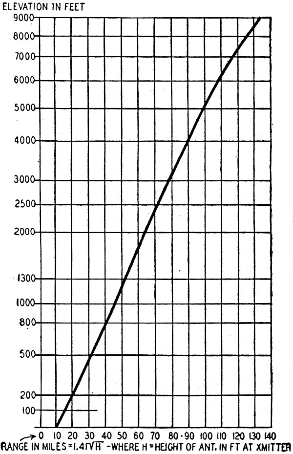
Fig. 9 - Chart shows range vs. antenna height. The higher the better - is a good rule for high-frequency as for all other antennas. Although the theoretical maximum transmission range is the optical horizon, some bending of the waves takes place through the atmospheric layers, and the formulas given below (including the chart of Fig. 9) take this refraction or bending of the waves into account. The formula for calculating the reception distance in miles is: D (miles) = 1.41 √(H (feet) ), where H is the height of the transmitting antenna. The receiving antenna is assumed to be at ground level. If the receiving antenna is high, the range is increased proportionately; and the formula below can be used for computing the probable maximum distance for regular reception. D = 1.41 √(Ht) + 1.41 √(Hr), where Ht = the height in feet of the transmitter antenna, and Hr = the height in feet of the receiving antenna.
Fig. 10 - A folded dipole for two frequencies.
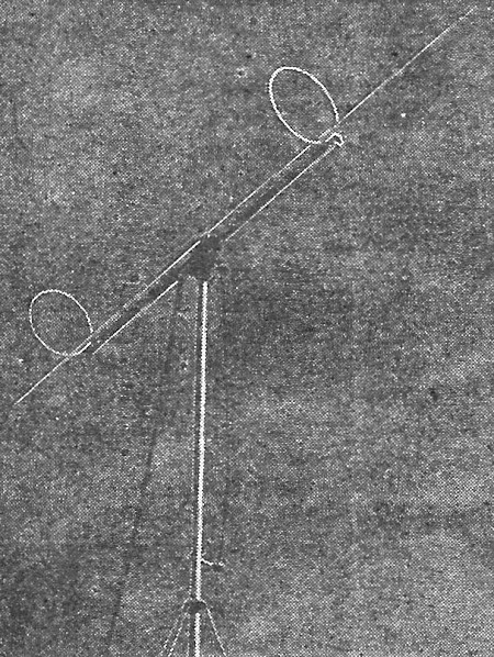
Fig. 11 - The adjustable-V antenna.
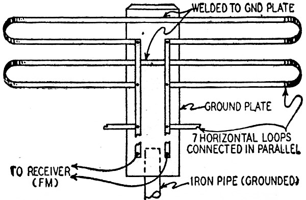
Fig. 12 - Part of a multiple doublet antenna.
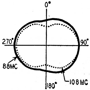
Fig. 13. - Broadband directivity pattern of multiple double antennas.
Fig. 14 - Antenna impedance vs. frequency. Mismatch may cause ghosts. The distance over which v.h.f. signals may be heard varies considerably; this fall, one of the editors of this magazine had occasional (but not 1oegular) reception from a dozen 88-108-mc FM stations, 150 to 500 miles away, using a simple dipole about 35 feet high. The calculated regular range for some of, these stations was about 50 miles, so reception was probably due to freak reflections in a sunspot maximum year, or in some cases due to greater than normal bending of the waves at the horizon. The distance over which v.h.f. signals can be heard regularly does not vary greatly. The formula gives a good average value. Long-Distance Reception For v.h.f. reception at the extreme limits of the regular service area of a station, the dipole antenna may be raised to an extra high elevation, but this is not always possible. A rhombic antenna is suitable for television or FM reception, as it covers a very wide band of frequencies, 60 megacycles for example when the antenna is designed for it. The rhombic is very sensitive to weak signals and is strongly directive. Charts and formulas for designing rhombics for different frequencies are given in radio textbooks and a number of special antenna handbooks are also published. A single wire several wavelengths long is another possible antenna for long-distance reception. New Types of h.f. Antennas Designers of h.f. antennas have developed a number of novel types, with broad frequency coverage. The Andrews Di-Fan TV and FM antenna is designed to intercept a broad band (all the TV and FM frequencies from 44 to 216 mc). The antenna is used with a 300-ohm line, and a performance curve shows it to be superior to a folded dipole. Another new departure is to combine 2 antennas in a single unit, one for the reception of the lower h.f. channels and the other for receiving the upper h.f. channels or frequencies. The 2 antennas are suitably joined by a special impedance-matching section. An array of this pattern is the Brach type 338 FM and TV (Fig. 10). The bands covered are 44-108 and 174-216 mc. It uses a 300-ohm line. Two folded dipoles are used. The cross-type antenna for omnidirectional FM reception is favored by several manufacturers, notably Brach and The Workshop Associates. The upper and lower dipoles which form the cross are joined through a quarter-wave matching section. A 300-ohm twin conductor or cable usually connects the cross antenna to the receiving set. The joint impedance of the combination is about 125 ohms. An adjustable V-type antenna is featured by Premax. The arms can be set at various angles to suit changes in polarization of the received wave. The impedance varies from 100 to 200 ohms, but may be matched by a 300-ohm line. The arms are of the proper length to resonate at the center of the FM band. (See Fig. 11.) A multiple FM folded-dipole antenna, as designed by Rauland, is shown in Fig. 12. It has 7 folded loops or dipoles arranged horizontally, and it tunes to all frequencies from 88 to 108 mc. The center of each loop is spot-welded to the ground plate. The antenna requires no special orientation. The broad directivity pattern is shown in Fig. 13. The average standing wave ratio is 2, and the surge impedance 300 ohms. The double dipole and reflector array shown in Fig. 6 is peaked for 62 mc (center of the lower television band). As the curve of Fig, 14 shows, the surge impedance varies from 100 ohms at the lower end of the band, to 350-ohms at the upper end, the average impedance being about 200 ohms. The standing wave ratio is also shown; if this falls somewhere between 2 and 3, it is considered a fair value. The Tricraft Products Co.'s antenna, developed in conjunction with the Belmont Radio Corp., uses 2 dipoles (see Fig. 15) to cover the 2 TV bands and also FM. It is matched by a 300-ohm line. A relatively thin dipole, (which is a half-wave long at 70 mc) is placed near a relatively thicker dipole cut to a half wave at 128 mc. The short, thick dipole is connected at its ends through inductive rings to the approximate midpoints of the thin, long dipole section. In the lower television band the antenna acts like a broad-band folded dipole tuned to approximately 65 mc, with the thin member resonant at about this frequency, and the short heavy antenna end loaded by the inductive rings at its ends. In the higher TV band, the long thin dipole is 1 1/2 wavelengths in the center of the band, and the short member is end-fed by means of the inductive rings connecting it to the long member, so that the currents flow approximately in phase in the 2 dipoles. All elements of the antenna are securely grounded to the support member, which permits grounding it to ensure lightning protection.
Fig. 15 - Interesting looking 2-band antenna.
Posted January 13, 2020 |
|