|
January 1948 Radio-Craft
 [Table of Contents] [Table of Contents]
Wax nostalgic about and learn from the history of early electronics.
See articles from Radio-Craft,
published 1929 - 1953. All copyrights are hereby acknowledged.
|
Prior to modern flat screen
LED, LCD, and (rarely anymore) plasma television displays, image projection
systems ruled. Cathode ray tubes (CRTs) dominated image displays from around the
1940 through the early 2000s. Prior to that electromechanical projection schemes
were used to basically magnify a small picture and display it on a larger screen
- either from the front or from the back. Some of the gizmos were pretty
complicated with whirling plates and clacking shutters.
Dr.
Vladimir Zworykin, who wrote this 1948 Radio-Craft magazine article, is widely credited
for making television practical with his image orthicon, or
iconoscope,
"camera" tube for capturing real-time moving images in the transmitter. He also
made significant improvements in the cathode ray tube for projecting the images
in the receiver. RCA, for whom Dr. Zworykin worked during CRT development, owned
a trademark on the name "cathode ray tube" until it released it to the public
domain in 1950. This article focuses primarily on the iconoscope.
Progress in Television

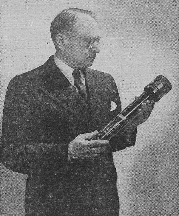
Dr. Vladimir K. Zworykin, shown holding the image orthicon, is one of the
engineers whose work created the science of television. He is still pioneering in
the television art, as well as in other advanced fields of radio and electronics.
America's foremost television-inventor, pioneer and engineer reviews recent developments
By Dr. Vladimir K. Zworykin
The end of the war emergency has seen the beginning of two developments in the
television field in America. The first is utilization of the accumulated experience
of the war and prewar years to create an extensive, high-quality television broadcasting
service. The second is the application of television techniques to an ever-increasing
number of peacetime industrial uses, a process which is bound to result eventually
in further advances in broadcasting technique.
The first development is, reflected in the increasing numbers of station-operating
licenses issued by the Federal Communications Commission, the opening of new concentric
cable and radio relay links between stations, heavy receiver production schedules,
and the blossoming of the characteristic television dipole antennas over the landscape.
By midsummer of 1947 there were 12 television broadcasting stations in operation
and a larger number under construction. Some 70,000 receivers had been installed.
The tools of this television system are tried and tested. Following the same pattern
of private sponsorship as American radio broadcasting, television programs provide
black-and-white transmissions with a 525-line, interlaced scanning pattern. Electronic
storage pickup tubes - in particular the iconoscope and the image orthicon - are
employed both in the studio and for spot pickup. In the receivers, kinescopes serve
to reproduce the image both for direct viewing and for screen projection. These
elements play a central role in most of the television equipment to be considered.
The most important common feature of the pickup tube under consideration, the
storage principle, is illustrated in Fig. 1. The light image of the scene to be
transmitted is projected on a photo-sensitive, insulating surface - the target or
mosaic. This surface is capacitively coupled to a metal backing, the signal plate.
The light image builds up, by photoemission, a charge image on the insulating surface.
This charge image is scanned by an electron beam. As a particular picture element
is scanned, the charge stored in the element by photoemission during the preceding
picture period is released and provides the picture signal current from the signal
plate behind the mosaic to the video amplifier input.
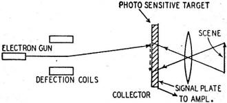
Fig. 1 - The storage action of a pickup tube.
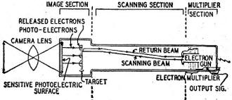
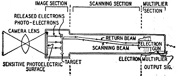
Fig. 2 - How the image orthicon tube operates.
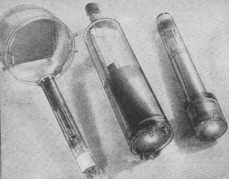
Fig. 3 - Iconoscope, orthicon and image orthicon. Size decreases
as sensitivity increases.
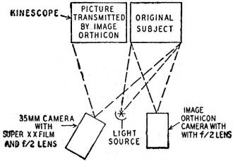
Fig. 4 - Experiment on orthicon sensitivity.
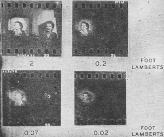
Fig. 5 - Results of the experiment of Fig. 4.
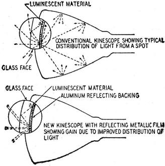
Fig. 6 - Effect of aluminizing screen surface.
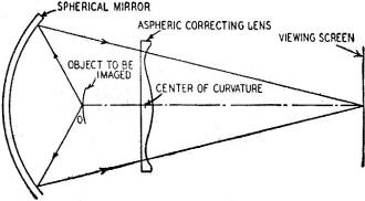
Fig. 7 - Principle of Schmidt optical system.
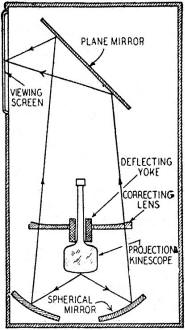
Fig. 8 - Schmidt-type television projection set.
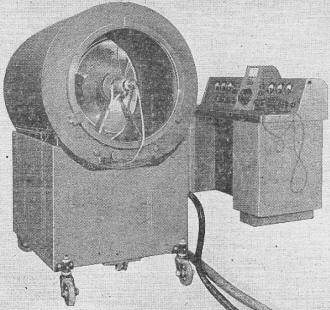
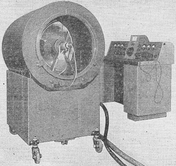
Fig. 9 - Large projection televiser designed for 5 x 7-meter
screen.
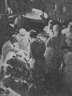
Fig. 10 - Television camera at Johns Hopkins Medical Center.
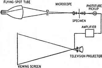
Fig. 11 - Action of the flying-spot microscope.
In the iconoscope the scanning beam has a velocity corresponding to an accelerating
voltage of about 1,000. For this velocity the secondary-emission ratio of the photosensitive
surface is much larger than unity. Accordingly the beam brings a scanned element
to an equilibrium potential which is sufficiently positive with respect to neighboring
collecting electrodes so that all secondary electrons but one per primary electron
are forced to return to the element. Under such circumstances only a small fraction
of the secondary electrons and photoelectrons emitted by the element reach the collecting
(anode) coatings on the tube walls. A majority of those which are not returned to
the element of origin are redistributed over the remainder of the mosaic surface.
This both reduces the efficiency of operation, and hence the sensitivity, of the
pickup tube and distorts the charge image formed on the mosaic by photoemission.
In practice, this distortion is rectified by the monitoring engineer by adding appropriate
"shading signals" to the picture signal.
The orthicon-short for orthiconoscope or "true iconoscope" - remedies these drawbacks
by reducing the velocity of the scanning beam on its approach to the target to such
an extent that the secondary emission ratio of the latter falls below unity; the
equilibrium potential of the target is now slightly below the potential of the cathode
of the electron gun, and the beam deposits just enough electrons on the target to
neutralize the positive charge stored by photoemission. The returning beam electrons,
just like all the photoelectrons and secondary electrons emitted by the target surface,
are collected by the anode.
Although the orthicon is, consequently, considerably more sensitive than the
iconoscope, perfectly linear in its response to illumination, and free from spurious
signals, it falls short of an ideal storage tube in two respects: (1) at very high
light levels the tube operation becomes unstable, since the target may become sufficiently
positive to pass over to its high-voltage equilibrium point under the scanning beam;
(2) the signal level is still sufficiently low so that noise introduced by the first
stage of the amplifier may impair the quality of the transmitted image.
The Image Orthicon
In the image orthicon1 (Fig. 2), the instability at high levels is
removed by providing a target screen at a voltage only slightly above the equilibrium
potential of the target to collect the electrons emitted by the latter. This makes
it impossible for any portion of the target to become sufficiently positive to result
in unstable operation. Furthermore, the signal level of the output is raised both
by inserting an image tube section ahead of the target and employing a secondary-emission
multiplier for the noise-free amplification of the signal current. The methods of
beam focusing (by a longitudinal magnetic field) and of beam deflection (by superimposed
transverse fields) are similar to those employed in the orthicon. They are designed
to produce a low-velocity spot, which is sharply focused at all points of the target.
Magnetic deflecting fields are employed throughout in the image orthicon, so that
the beam electrons which fail to be deposited on positively charged portions of
the target return along paths close to the incident beam to the area of the anode
disk surrounding the beam-defining aperture. Here they eject secondary electrons.
The electrostatic fields surrounding the anode disk are such that these secondary
electrons are drawn over into the first stage of a "pinwheel" secondary-emission
multiplier which surrounds the gun structure. Repeated secondary-emission multiplication
at the vanes of 5 successive pinwheels results in a total gain from 200 to 500.
The amplified return-beam current, representing the difference of the constant scanning-beam
current and the variable picture-signal current, provides a high-level input for
the succeeding video amplifier.
The formation of the charge image on the target presents some new features. The
light image of the scene is projected on a transparent photocathode, which is maintained
approximately 300 volts negative with respect to the target. The photoelectrons
emitted as a result are accelerated and focused by the longitudinal magnetic field
on the target, ejecting a multiplicity of secondary electrons. Picture elements
of the target which correspond to bright portions of the image assume consequently
a positive charge; the secondary electrons are drawn to a high-transmission, 20-40-mesh-per-millimeter,
metal screen placed just in front of the target.
The target itself is a very thin, high-conductivity glass film, stretched on
a metal frame. Although potential differences between its faces are substantially
neutralized by conduction in the course of a frame time, leakage from picture element
to picture element is too slight to result in an appreciable reduction in the contrast
and resolution of the picture.
The relative dimensions and general structure of the 3 pickup tubes discussed
are well brought out by Fig. 3. Increasing complexity of construction has not brought
increase in bulk.
The extraordinary sensitivity of the image orthicon is illustrated by the experiment
shown in Fig. 4. An image orthicon camera and a photographic camera employing high-sensitivity
(Eastman Super-XX), 35-mm film were both trained on the same subject. A television
receiver connected to the image orthicon camera was placed next to the subject.
Both cameras were provided with f/2 lenses and exposed for 1/30 second (corresponding
to the standard television frame time). The result of attenuating the illumination
provided by a 40-watt incandescent lamp with neutral filters is shown in Fig. 5.
It is seen that the subject is recorded by both cameras only at the maximum subject
brightness of 2 foot-lamberts or, approximately, 2 millilamberts. At the lower intensities
only the television image remains, which is still readily recognizable when the
illumination has been reduced to a hundredth of its original value.
The viewing tube, or kinescope, has undergone only minor changes in recent years.
The most important of these have increased the image brightness of projected television
pictures. Considerable gains have been recorded both in the light emission of the
projection kinescopes themselves and in the efficiency of the optics employed to
project the pictures.
Enhancement in the emission of the projection tubes has been achieved by depositing
a thin metal film - transparent to the beam electrons but reflecting for light -
over the surface of the luminescent screen. The optical effect of such a film on
light emitted backward by the luminescent screen is indicated in Fig. 6. In a tube
with an untreated screen this light, which is lost for the formation of the image,
may in part reach other portions of the screen, reducing contrast. The metal film2
both adds this light to that emitted in a forward direction and prevents this contrast
reduction. An even more important factor with high-voltage operation is that the
metal film, maintained at anode potential, prevents the screen from charging negatively.
Without such a film this charging process may reduce by a large factor the kinetic
energy with which the electrons impinge on the screen so that the energy available
for conversion into light is greatly decreased. A final advantage of the metal film
is that it absorbs negative ions originating in the cathode region of the gun, preventing
the appearance of "ion spot" without requiring special ion-trapping arrangements.
Reflective Systems
The substitution of reflective projection systems with aspheric correction for
the conventional projection lenses has led to gains by a factor from 5 to 7 in the
optical efficiency of projection systems.3 The principle of the new optical
system is shown in Fig. 7. The television image formed on a curved kinescope face
is projected by a concentric spherical mirror on the viewing screen. Such a system
is spherically symmetrical about the common center of curvature of mirror and tube
face, and hence provides an image field free from optical defects apart from spherical
aberration. If the latter is corrected by placing a weak aspheric lens at the center
of curvature, there results a wide-angle, large-aperture system free from all lower-order
optical defects. The preparation of the aspheric lens, it is true, presents a difficult
mechanical problem. However, a plastic molding technique makes it possible to prepare
large numbers of such lenses from a single steel master. This procedure has rendered
it economically feasible to employ reflective projection systems in home receivers,
arranged as shown in Fig. 8. The image on the tube is projected upward and deflected
by a 45° mirror onto a vertical directional viewing screen. The optical efficiencies
of such systems have been found to range from 18 to 35%, as compared to 4-5% for
an f-2 projection lens. Fig. 9 shows an earlier television projector operating on
the same principle, but designed to cover a motion picture theater screen 5 X 7
meters in dimension.
The equipment described so far primarily finds application in current television
broadcasting and reception. However, its utility is by no means limited to broadcast
television. Numerous other uses may be conveniently grouped under the heading "industrial
television."
Many Other Uses for Television
An application of obvious importance is the employment of television equipment
to observe industrial processes which are either inaccessible or dangerous to human
beings; the Bikini atomic bomb observations are a relevant example. Other uses are
deep-sea observations and the surveillance of boilers in power plants. A similar
type of application is the watching of a series of widely separated, automatic substations
from a conveniently located . central point. Here television enables one individual
to observe simultaneously events taking place at widely separated points. The converse
problem, of permitting a group of individuals, too large for direct viewing, to
observe the same point is met not only in broadcast television, but also in department
stores, to let customers view fashion exhibits at widely separated sections of the
store; at conventions, to permit an overflow audience to watch the proceedings;
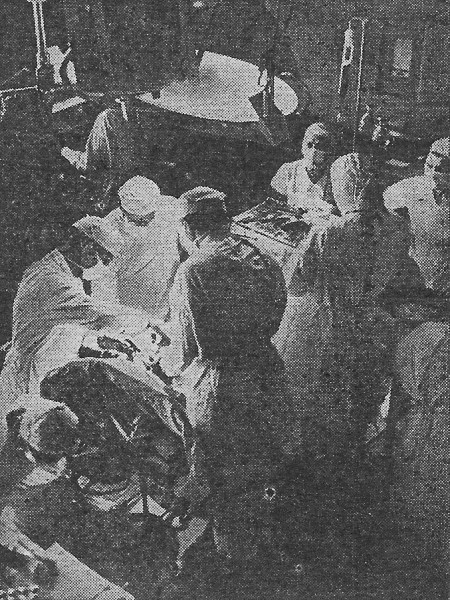
and, perhaps most significantly, in medicine, to give consulting and visiting physicians
an intimate view of an operation without interfering with its progress. Fig. 10
shows a television camera suspended for this purpose directly above the operating
table in an operating room of the Johns Hopkins University Hospital.
Television techniques also find valuable application in fields which, at first
sight, seem only very remotely related. One of these is projection microscopy. Many
years ago the ultra-violet and infrared sensitivities of the iconoscope and the
image tube were utilized to permit the eye to see enlarged images of microspecimens
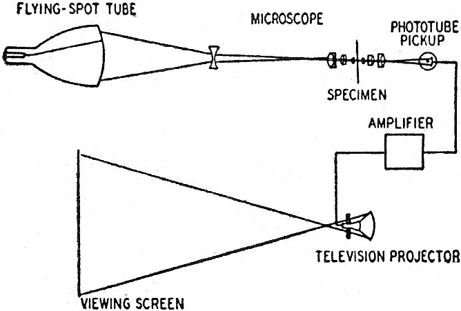
formed with these invisible radiations. The flying-spot microscope, shown schematically
in Fig. 11, serves instead to present the greatly enlarged microscope images to
extended audiences, with a brightness which is independent of the illumination of
the specimen. For this purpose a television scanning pattern formed on the very-short-persistence
fluorescent screen of a cathode-ray tube (a "flying-spot tube") is imaged by a high-resolution
optical microscope to greatly reduced scale on the microspecimen. The transmitted
light is directed by a second microscope objective onto the cathode of a multiplier
phototube. The amplified output signal of the latter modulates the beam current
In the kinescope of a television projector which forms a greatly enlarged image
of the microspecimen on a screen, its deflection being synchronized with that of
the flying-spot tube.
Many of these developments are still in an experimental stage. However, they
illustrate the fact that television broadcasting represents but one phase of the
application of television techniques. Industrial television offers a possibly even
broader range of opportunities to the researcher and experimenter and may be expected
to develop into a tool of increasing value in the coming years.
1 A. Rose, P. K. Weimer, and H. B. Law, "The Image Orthicon - A Sensitive Television
Pickup Tube," Proc. Inst. Radio Engrs., Vol. 84, pp. 424-432.
2. D. W. Epstein and L. Pensak, "Improved Cathode-Ray Tubes with Metal-Backed
Luminescent Screens," RCA Review, Vol. 7, pp. 5-10, 1946.
3. D. W. Epstein and I. G. Maloff, "Projection Television," J. Soc. Motion Picture
Engrs., Vol. 44, pp. 443-455, 1945.
Posted October 29, 2019
|