Transmission Lines
|
|||
Is there such as thing as too many articles on transmission lines? I think not, at least for most visitors to RF Cafe. Since the fundamentals of transmission lines have not changed in the last century, it really doesn't matter when an article was written. This one covers the basics of impedance and wavelength, and then delves briefly into the subjects of antenna feeder transmission lines and using transmission lines as impedance transformers. As with most topics these days, there are many software programs available that will calculate parameters for you, but successful setup and operation requires a solid understanding of what is happening with your electronic gear, antennas, and the transmission lines that provide the interfaces. Transmission Lines By M. N. Beitman*
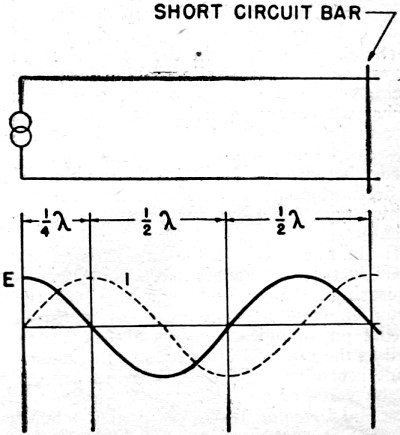
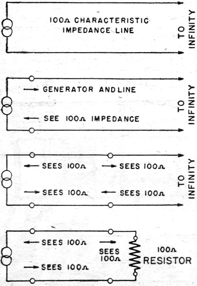
Transmission lines are used mainly for coupling the antenna to a transmitter which may be located some distance away. Besides this primary application, lines are used as impedance matching devices (like transformers); in place of lumped series or parallel tuned circuits, as all types of filters; and for high frequency measurements. To understand how these functions are obtainable from lines which at lower frequencies (audio or 60-cycle power frequencies) are considered simply as conductors of electricity possessing only resistance, some new concepts must be introduced. Even a straight short piece of wire has both capacitance and inductance. Focus your attention on a very tiny piece of the wire at one end and another tiny piece of this same wire a short distance away. Certainly these metal pieces (parts of the wire), as such, are separated by the wire between them which in turn may be considered as a resistor. This wire does have resistance and this resistance produces a voltage difference (drop) between the two tiny parts of the wire. The two tiny pieces of wire form also two plates of a condenser, with the surrounding air acting as the dielectric. No fixed quantity of air, or any special section of air, serves as the dielectric, but all air (and all other insulators in the universe for that matter) serve as the dielectric of this condenser which we have just described. In a similar fashion, all other tiny portions of our wire, form condensers with each other. In a like manner, it can be shown that the magnetic field produced by any infinitesimally small portion of the wire, cuts other sections of the wire and the effects of self-inductance are present. We begin to see that any wire which may ;form a transmission line has, besides resistance, capacity and inductance. Also the leakage present may be expressed as conductance. Let us connect two adjacent, parallel wires to a high frequency generator (a radio transmitter will do). In a practical experiment, these parallel wires (or line) could be made by mounting two lengths of copper wire on supporting insulators, so arranged that the wires would run parallel, perhaps two inches apart. The line could be coupled to the transmitter by being connected to a link coil placed near the final tank coil. The electrical energy proceeds along the line at a definite rate. If our transmitter is producing a sine wave shaped voltage, as is the usual case, sine wave currents and voltages occur at all points along the line but with the actual instantaneous values at time displacements which depend on the distance from the generator. The end of the line may reflect voltage and current waves. These may reinforce or reduce the original waves. In particular, if the line is an odd multiple of a quarter wave length (1/4, 3/4, 5/4 of a wave length) and is properly terminated for the purpose, the reflected energy will be in phase with the new forthcoming waves, and large standing waves will be developed. These standing voltage waves can be detected with a neon bulb, while the current standing waves can be observed with a pilot bulb connected to an exploring single turn loop. The voltage and current standing waves are 90 electrical degrees out of phase. See Fig. 1. The fields produced by the two wires of a line oppose each other and very little radiation takes place. The main losses are the actual resistance losses of the conductors used. A resonant line, therefore, has small losses and a high Q. As. the two wires of a resonant line are spread apart, radiation increases. Radiation resistance (losses of energy from the system because of radiation) also increases. Radiation can be prevented by using a coaxial cable. Such a cable may be flexible or solid and has one small wire conductor completely surrounded by (but insulated from) a conducting tube serving as the second conductor. The characteristics of coaxial cables depend primarily upon the ratio of the inside diameter of the pipe to the diameter of the center wire, and upon the dielectric. If the line we used for our explanation were infinitely long (that is, continued without an end), there would be no reflection from the far end, since this end would never be reached. There would be no standing waves on the line for any frequency since there would be no reflection. In looking into the line, the generator would see a definite value of impedance which depends on the spacing of the conductors, size of the wire selected and the dielectric employed. This impedance is called the surge or characteristic impedance. Suppose we cut our 'line a short distance from the generator. (A few feet of wire removed from an infinitely long line, leaves the line still infinitely long.) Looking into the infinite line remaining, the short line connected to the generator will see the characteristic impedance of this infinite line. See Fig. 2. Let us say that in this case the characteristic impedance is 100 ohms. If we replace the infinite line with a 100-ohm resistor, the short line connected to the generator will behave exactly the same and will not distinguish between a 100-ohm resistor, or a 100-ohm characteristic-impedance infinite line. In turn, the radio frequency generator connected to the input of our short line will see a 100-ohm impedance whether the line is infinite in length and has a 100-ohm characteristic impedance, or whether it is of finite size, and is terminated in its characteristic impedance of 100 ohms, as in this case. This is indeed a simple way to increase the length of a line to infinity, and is of the greatest value in practical applications. Antenna Feeders
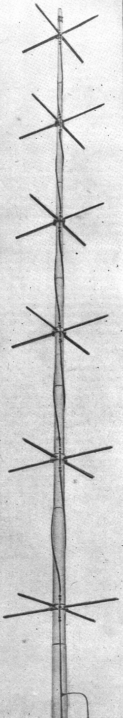
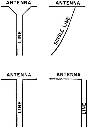
A non-resonant parallel wire line radiates a negligible amount of energy and does not produce standing waves if it is terminated in its characteristic impedance. The effective voltage and current vary along an antenna, giving different impedance values between any two points along the antenna. A non-resonant line may have its two wires make contact to the antenna, a short distance on each side of the antenna center. By moving the contact points closer together or further apart, the impedance needed to match the line is obtained. Maximum power transfer will also occur when impedances are correctly matched. A single wire transmission line may be used. In this case, the wire is connected to a point of correct impedance. This point is usually some distance away from the center of the antenna. The return circuit is completed through the antenna-to-ground capacitance. The proper adjustment of a non-resonant line can be checked by striving to obtain absence of current or voltage maximum points along the line. Fig. 3 shows several methods of connecting a transmission line to an antenna. A line a quarter of a wave length long, connected to a radio frequency generator at one end and left open at the other end, will behave as a series resonant circuit. For example, using a frequency of 300 megacycles, which corresponds to a wave length of one meter, the line will be 1/4 of a meter long. At and near this frequency this line will behave as a series circuit similar to one having a condenser and coil of values which would resonate at 300 MC. At frequencies considerably removed from resonance, the behavior of the line and the lumped constants resonant circuit will differ. In a like manner, a quarter wave length line short-circuited at the far end will behave as a parallel resonant circuit. Lines of a quarter wave length dimension are usually employed in practical circuits. Lines of longer physical length may be employed, but they produce larger losses, are bulky, and require more material. A short-circuited quarter wave length line is often used as the tank circuit of a high frequency transmitter. Such a line is easier to adjust than a circuit made up of a coil and condenser and, further, has a much higher Q (smaller losses) at the frequencies employed. The short circuit at the far end need not be made; in practice, a condenser of about .0005 mfd. may be used. This capacity serves as a practical short circuit for the R.F. employed. At the short-circuited end, the current is maximum, since a direct path exists between the wires of the line; while the voltage is minimum (zero) because of the short. At the generator side these conditions are exactly reversed; the voltage is maximum and the current is minimum. See the illustration of the current and voltage distribution. Lines As Transformers The voltage varies along a short-circuited quarter-wavelength line, being maximum at the generator end and zero at the short circuit. The current ,variations are in reverse to the voltage changes. If the generator is left connected at one end, any voltage from maximum to zero may be obtained by placing a suitable resistive load at a suitable point along the line. This action corresponds, to that of a' step-down transformer. Should the load be connected to the open end instead of the generator, while the generator is connected to some intermediate point of the short-circuited quarter wave length line, a voltage step up will result. Transformers which step voltages up and down also match impedances. This is a more useful application of the line. Special short-circuited lines, known as stubs, may be used to tune out the unwanted reactive component of antennas or other elements, leaving only the resistive .component to which power can be delivered at far greater efficiency. This is a very important application and is used extensively with antennas for high frequency work. Radio Servicemen are accustomed to visualizing radio filters as being made up of condensers and inductances. Since we now know that lines can be made to act as series and parallel circuits, they may be employed instead. Because lines have much smaller losses, they form filters with much sharper characteristics. For Measurements It is very difficult to make tests and measurements at very high frequencies. Usually these measurements must be made indirectly or by means of a comparison. Because the physical dimensions of a transmission line are easily measured and because these dimensions are related to electrical properties such as frequency, impedance, etc., transmission lines serve a useful purpose for making measurements in the radio laboratory. The value of an unknown high frequency can be determined by connecting the source of energy to a line and detecting the distance between successive voltage maximums. Under proper adjustments, this distance will be equal to one-half the wave length of the signal being considered. * Supreme Publications, Chicago
Posted October 26, 2020 |
|||