|
June 1945 Radio-Craft
 [Table of Contents] [Table of Contents]
Wax nostalgic about and learn from the history of early electronics.
See articles from Radio-Craft,
published 1929 - 1953. All copyrights are hereby acknowledged.
|
Although this "Tuning on the UHF"
article refers to a specific radio band popular for "shortwave listening," the information
therein is generally applicable to any band. It appeared in a 1945 issue of
Radio-Craft magazine, at a time predating widespread ownership of television,
where instead of watching the boob tube many people enjoyed tuning in broadcast
stations from across the country and across the globe. Radio was still a mysterious
and magical thing. A tapped coil (inductor), variometer, permeability tuner, standard
coil-condenser (inductor-capacitor), and
General Radio butterfly tuner
are possible methods for any frequency typically used at the time, but the transmission
line tuner was only practical with the higher frequencies.
Tuning on the U.H.F.
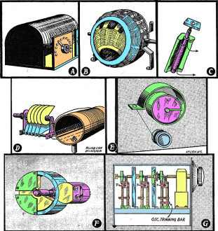
Tuning methods used in the past. (A) Tapped coil, (B) Variometer,
(C) Permeability tuner, (D) Standard coil-condenser, (E) Capacity-inductance variometer,
(F) General Radio butterfly tuner, (G) Circuit using transmission lines.
By I. Queen
The resonant frequency of series tuned circuits is varied by changing either
capacitance, inductance or a combination of them, the fundamental formula being
expressed f = 1 / (2π√[LC]).
Methods which are used are: Sketches A-D tapped coil, variometer, permeability
tuning, and the "standard" variable capacitance circuits.
The first tunes by steps, but is simple, and may be used in conjunction with
a crystal receiver and home-made coils or where reception of only two or three high-powered
stations is desired. The second offers mechanical difficulties, but permits gradual
control and can be constructed to give zero inductance. The variation is due to
mutual inductance which aids or opposes as the rotor turns within the stator.
Permeability tuning generally has only a limited range of control and has lower
losses than the two previously mentioned methods. Tuning takes place as a result
of the relative movement within a coil of a powdered iron core.
The great advantages of variable condenser circuits are ease of ganging convenience
of manufacture, and low loss, as well as the reasonable range of frequencies which
may be covered by a single turn of the dial. A variation of this method is automatic
push-button tuning wherein small condenser trimmers are pre-set and switched in
for desired stations.
For Higher Frequencies
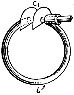
Fig. 1 - An early method of shortwave tuning.
When oscillators, received or transmitters are designed for the higher frequencies,
mechanical and electrical difficulties appear. Both L and C must be made inconveniently
small and special precautions taken to decrease losses and body capacity. It should
be remembered that tubes and wiring present a definite L and C of their own, which
becomes important at such frequencies.
One method used by amateurs in pre-war transmission and reception consisted of
an assembly such as Fig. 1. The tuning coil is decreased to a single turn and the
condenser to two small plates, one stationary. A long insulated shaft controls the
other plate. All unnecessary supports are eliminated and only low-loss material
such as polystyrene can be tolerated as insulation.
At frequencies of the order of 250 Mc, this circuit begins to show comparatively
low values of Q = (reactance/resistance) due to transit time differences. It may
at first glance seem a trivial matter, but theory shows that electrons situated
at the center of one condenser plate will reach the other condenser plate before
electrons which happen to be at an edge, and the optimum effect will not be obtained.
An improvement is due to two inventors, R. L. Harvey and H. G. Fisher, who have
developed the circuit shown in Fig. 2 and sketch E, where L and C are distributed.
The space-wound flat spiral S may be of phosphor bronze or silver-plated steel,
the end of which is controlled for tuning by a winch W and cord C. The spiral may
be contracted or expanded by winding up the cord.
Typical Q values obtainable with the circuit are plotted in Fig. 3, which may
be contrasted with a typical Q of about 200 at 250 Mc for Fig. 2. Typical ribbon
dimensions are 1/4 inch width and 30 inches total length.
The Butterfly Circuit
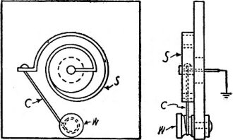
Fig. 2 - A capacity-inductance variometer.
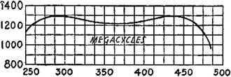
Fig. 3 - "Q" value curve of the above circuit.
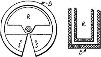
Fig. 4 - The General Radio "butterfly" circuit.
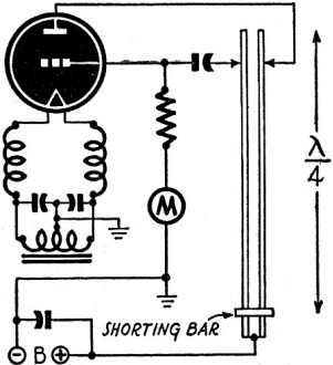
Fig. 5 - A tuner with distributed constants.
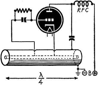
Fig. 6 - Concentric-line tuner - UHF plumbing.
Transmission-line tuning elements are used in combination with
the standard type variable condenser in this ultra-high-frequency, which is covered
by Patent No. 2,366,750.
General Radio Co. recently introduced a novel tuning unit which may be used for
oscillators, receivers, etc. It is known as the butterfly circuit from its general
appearance and may be constructed to cover such frequency ranges as 220-1100 Mc
and 900-3000 Mc with no moving contacts. Both L and C are varied simultaneously.
As illustrated in Fig. 4-a and sketch F, two stator members, generally in quadrant
shape, are supported by an annular band to which the stator is soldered. The external
terminals are attached to the opposite stators, S. The rotor R is mounted on
an insulating shaft and is concentric with the band B.
The entire assembly between the terminals then consists of two condensers in
series, each being formed by one stator and the rotor. Furthermore, the band is
the inductance and shunts the capacitance. The rotor has only slight clearance with
respect to the inside of the band which is relatively deep (Fig.4-b).
The magnitude of the inductance due to the band depends upon the amount of flux
within it. As the position of the rotor is changed it restricts the area through
which the flux may pass, changing the inductance. Its relative position with respect
to the stators obviously also affects the capacitance. The result is an unusual
tuning circuit providing a wide U.H.F. band and containing no moving parts which
might give trouble at exceedingly short wave lengths.
Transmission Line Tuning
The difficulties of obtaining sufficiently small concentrated L and C at the
very high frequencies may readily be appreciated. The value of Q which determines
frequency stability and efficiency becomes comparatively low at such short wave
lengths. A convenient method is the use of transmission lines, either concentric
or parallel.
Figs. 5 and 6 illustrate the use of such lines. Both are seen to be the equivalent
of Hartley oscillators. Chokes are used to keep R.F. out of the tube filaments.
The lines are approximately a quarter wave-length long and may be varied by changing
the position of the shorting bar. The con-centric line performs similarly to the
other. Its advantage is the elimination of radiation.
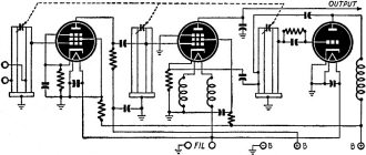
Use of transmission line segments for tuning an U.H.F. receiver is made by George
E. Pray of Clearfield, Penn., in his recent invention as illustrated, Fig. 7. High
stability and accurate gang tuning are obtainable.
A length of line, shorted at one end and slightly less than a quarter-wave in
length is used as an inductance, tuned by a small condenser. Adjustable taps are
provided, the grids being tapped down to match the tube input impedances. The first
stage is an R.F. amplifier, the second a mixer, and the last is the oscillator.
The grid of the latter is connected to a suitable tap on one leg, the plate to a
point on the other leg and the cathode to ground. Another tapped connection (through
a condenser) leads to the mixer cathode where heterodyning takes place. The mixer
output (after proper by-passing) passes on to the I.F. amplifier, not shown.
The physical construction of such a receiver is shown in sketch G. The vertical
transmission lines are shorted at the bottom and the ganged tuning condensers mounted
above. Small trimmers are shown at T. These may be individually adjusted by the
service man. The right-hand circuit is the oscillator. Note that a slider bar is
provided to trim it to correct frequency.
No doubt much of the tuning at ultra-high frequencies will be accomplished by
means not now common. The use of cavity resonators is especially indicated.
These have been described in past issues of the magazine (Tube of the Future,
October, 1944, and Klystron Circuits, May, 1945). Another type of tube is that in
which internal capacities or element spacings have been reduced to the ultimate,
as in the acorn and disc-seal types. Such tubes will no doubt be used with some
of the circuits shown above, to reach otherwise unachievable frequencies.
Circuits and tubes, details of which have not yet been released to the public,
will no doubt play their part in extending the spectrum to frequencies entirely
unusable today.
Let us not, however, be too hasty in abandoning the standard tubes. They have
shown an astounding ability to operate on higher and higher frequencies. Technicians
will remember the days when it was considered necessary to "debase" a tube to work
on 80 meters. Today the same tube is used without hesitation in the 42-megacyde
region.
There is every possibility that at least over part of these ranges, standard
tubes such as those now manufactured for television may be used in conjunction with
tuning circuits like those described above. Such circuits would possess the advantages
of cheapness and wide tuning range probably unobtainable otherwise. For this reason,
if for no others, these circuits deserve our attention.
Posted November 8, 2021
|