Two New Approaches to Amplification |
|
If somebody today told you there are "Two New Approaches to Amplification," one being a Spacistor and the other a Solion, you would be justified in thinking he was putting you on - especially the Spacistor. In 1957 when this article appeared in Radio-Electronics magazine, you would more likely gasp in awe at the mere mention of such a Space-Age sounding devices. In fact, both devices were real, and were stepping stones in the evolution from point-contact transistors to molecular diffusion semiconductor junctions. They were more mechanically rugged than the point-contact transistors, worked at higher frequencies, and had higher current and voltage (and therefore power) handling capabilities. This is an interesting and important part of semiconductor development history. Two New Approaches to Amplification
By Eric Leslie (Top) (Bottom)
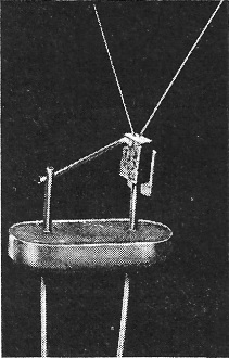
Spacistor Collector vertical rod at bottom right; base, rod slanting to bot-tom left; injector, left slanting cat-whisker; modulator, one at right. Within the past few months two new amplifying devices have appeared in the field where for so many years de Forest's electron tube ruled alone, moving aside a little only in the past decade to permit the transistor to do some of its jobs.
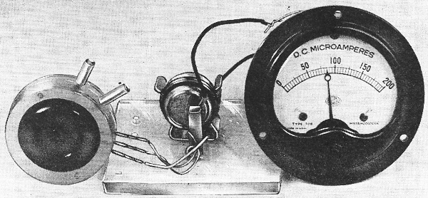
Solion (left) with special 0.9-volt battery (center) and an indicating meter (right), as used to measure moderate sound pressures. One of the new devices, Raytheon's Spacistor (Radio-Electronics, September, 1957, page 8) looks like a member of the transistor family. The other, the Naval Ordnance Laboratory's Solion (rhymes with Napoleon) ("Electro-chemical Units," Radio-Electronics, August, 1957, page 12), is like nothing else in this world. A flat cylindrical cell, which may be less than 2 inches across, divided or partly divided into two sections and filled with an electrolyte, it is a closer relative to the old wet cells that used to operate doorbells than to anything now used in the electric-electronic field. Yet it can measure pressures, flows, accelerations, and performs other functions which would otherwise require expensive, complex and bulky equipment. Operating on just under 1 volt, it runs for such long periods of time on an electric cell (battery XA-10B) specially constructed for it as to make even the transistor look like a current hog. Neither of these devices has reached the commercial market, and it is still too early to predict what part they will play in an electronic world where the tube and transistor have already proved themselves practical and versatile amplifiers. The Spacistor is expected to find its most useful applications in the uhf field; the Solion is limited to a top of 400 cycles at present, but can operate from there down to dc. It can also be used as a transducer to turn electric into mechanical energy.
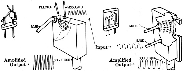
Fig. 1 - Two amplifiers compared. Spacistor - High voltage is applied between collector and base in direction to produce strong electric field and practically no current. Electrons injected into this field flow very rapidly to collector. Flow is modulated by signal applied between base and modulator, which acts like vacuum-tube grid. Transistor - Similar but lower voltage is applied between collector and base. Since emitter (in n-p-n transistor) is more negative than base area near it, it injects electrons, which flow to positive collector (at lower speed than in the Spacistor, because of lower collector voltage). Signal to be amplified is applied between base and emitter, current from which increases and decreases as it becomes more or less negative with respect to base. Action is same in p-n-p transistor, with reversal of voltages and current flow.
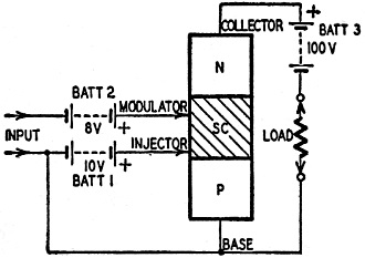
Fig. 2 - Idealized cross section of an experimental Spacistor. The very name of the Spacistor puts it in the solid-state amplifier family, whose best known member is the transistor. But this semiconductor device acts in many ways more like a vacuum tube than a transistor. (See Fig. 1.) The Spacistor operates at 100 volts; transistors are commonly low-voltage devices. Transistor output and input impedances are low; those of the Spacistor are high, even higher than for vacuum tubes. Transistor input capacitances, conversely, are high; the Spacistor's lower than those of vacuum tubes. The transistor's most serious limitation has been frequency. Readers remember when commonly available ones would work well over only a little more than the audio range. The frequency limit has been pushed steadily upward since that time, but is still well below that of vacuum tubes. One reason for the frequency limitations of the transistor is the slow diffusion of charge carriers (electrons or holes) through the base region. The applied voltages are usually low, and little push is applied to the charge carriers. Therefore, they move at a relatively low speed and when faced with rapid alternations of signal current just can't get to their destinations rapidly enough to produce an output exactly mirroring that of the input. In the language of the scientists, the electric field in which they move doesn't give them enough acceleration. A vacuum tube - with a drop of usually more than 100 volts between cathode and plate - has a strong field, and electrons are hurried right along in it. The same is true of the Spacistor, where 100 volts is applied across the body of the semiconductor, between collector and base in Fig. 2. The unit is a p-n junction hooked up in reverse bias (the direction that opposes current flow). Thus, there is a sharp potential gradient throughout the Spacistor, and we find a heavy space charge somewhat like that in a vacuum tube. This charge exists to some extent throughout the semiconductor, but is much heavier in the area marked SC. In this area particularly, moving charges are speeded by high voltage across the Spacistor body. So the problem of speeding up the charge carriers is solved. All that remains now is to get some charge carriers to speed up. We also have to control our stream of charges so as to get amplifier action. The tungsten-wire contact marked INJECTOR supplies the charges. It is connected to the base through a battery (BATT 1) which biases it slightly more negative than that part of the base with which it is in contact. Therefore it emits electrons into SC, the space charge area. The flow of electrons from the injector is limited by the backward pressure of the space charge, as in a vacuum tube. The MODULATOR is placed a little farther along the body of the Spacistor and is also biased (with BATT 2) to be somewhat more negative than the area under it. But it is doped with a little p-type material, and thus forms a p-n junction with the underlying semiconductor. Since its bias is negative, it can emit no holes into the base and therefore draws no current. The input signal is applied between the modulator and the base. The modulator acts like the grid of a vacuum tube; changes of voltage on it vary the current from the injector. The DC bias voltage on the modulator also makes it act something like the screen grid in a vacuum tube. The field due to this voltage is felt through the whole space-charge region and has a greater effect on the no-signal current from the injector than does the voltage from BATT 3, across the whole Spacistor. Thus it tends to prevent the injector current from being affected by changes in the voltage between base and collector. This keeps the output impedance reasonably high - in excess of 30 megohms for an injected current of 30 ma. (The input impedance is likewise high - also about 30 megohms.) The Spacistor is still in the early experimental stages and has not yet been tested to the limits of its capabilities. No checks at very- or ultra-high frequencies have been run, and the full amplifying power of the device is still unknown. Low-frequency power gains of 70 db and voltage gains of 3,000 have already been obtained from experimental units. Transconductance of present Spacistors is considerably below that of good vacuum tubes, but is comparable to that of dry-cell types. The Spacistor's output capacitance is extremely low - values of less than 1 μμf are entirely feasible - and it is expected that amplifiers can be built to operate at frequencies higher than 1,000 mc. Another advantage of the Spacistor is the isolation of input and output circuits by the modulator's screening action - a valuable feature in multistage circuits. It is further expected that it will be possible to construct Spacistors from much higher-temperature materials than transistors. The Ionization Cell
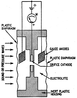
Fig. 3 - Detector of low-frequency sound or pressure waves.
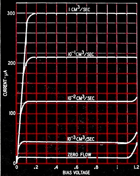
Fig. 4 - Response of cell of Fig. 3 as signal is increased. Many of us were given some idea of ionic action in our student days. In practical life, the flow of electrons has so far overshadowed that of ions that we may have forgotten that ions can carry current as well as electrons. Yet the ion still does play its part in our everyday life. It does useful work in gas tubes, like mercury-vapor rectifiers, thyratrons and voltage regulators, and is even more common in electrolytic capacitors, where ions actually form one of the plates. A more conspicuous (but less useful!) form of ionic activity is corona discharge, ever more familiar with increasing voltages on TV tubes. Ionization is the breaking down of atoms under electric stress. An atom so broken down may lose an electron, and be dissociated into a negative electron and a positive ion. Or it may gain an electron and become a negative ion. An ion, then, is a charged particle of matter - an atom that has gained or lost one or more electrons. Ions may be made by collision. In a mercury-vapor rectifier or thyratron, electrons on their way from cathode to anode knock electrons out of the gas atoms they run into on the way. These electrons accompany the first ones to the plate, increasing the tube's current output. Ions may also be made chemically. Electrolytes are chemical solutions whose constituents may be ionized. A very common example of such ionization is the electric primary cell (a flashlight battery is the most common example). Chemical action dissolves zinc atoms out of the can. They leave in the form of positive ions, leaving electrons behind them, and unite with negative ions of chlorine to form zinc chloride. Energy is released by this chemical reaction; electrons piled up in the zinc electrode (the can) constitute a negative voltage and can be made to do work on their way back to the positive (carbon) electrode. In some types of electrolytic cells we may put an external source of electricity across the electrodes instead of expecting energy from the cell itself. (The electrolytic capacitor again comes immediately to mind.) A cell with two electrodes of the same metal and an electrolyte composed of a salt of that metal can be used in electro-plating. Atoms go into solution as positive ions at the positive electrode, each atom leaving an electron behind. These ions drift toward the negative electrode, where each one picks up its missing electron and again becomes an atom of the metal. (If the negative electrode is not of the same metal as the positive one, it will be plated with metal from it.) The Solion A third type of electrolytic cell - the one used in the Solion - is one in which the electrodes take no part in the action. A typical Solion has platinum electrodes and a mixture of iodine molecules and potassium iodide in solution. The potassium iodide breaks up into positive potassium and negative iodide ions. The iodine molecules, drifting to the negative electrode at a rate virtually independent of the low voltage which is applied to the Solion, acquire electrons and become negative iodide ions. These ions move to the positive electrode, give up their electrons, again become iodine molecules. The quantity of electric current that will flow is controlled by the rate at which iodine molecules are broken down into iodide ions at the cathode (negative electrode) rather than by their reformation into iodine molecules at the positive electrode. Hence the current flow is independent of voltage and depends on factors such as stirring (movement of solution past the cathode).
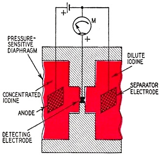
Fig. 5 - Separated detector measures unidirectional liquid motion; acts as rectifier on back-and-forth flows.
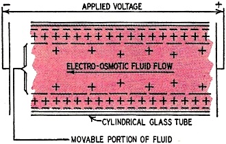
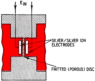
Fig. 6 - How an electro-osmotic flow is produced.
Fig. 7 - Voltage applied to electro-osmotic cell produces liquid flow. Thus we can use mechanical energy (stirring) to regulate electrical energy or convert mechanical energy to electrical energy. The first application of such an effect that comes to mind is a flow meter, and the Solion can be used for that purpose. Fig. 3 is an example of a flow meter. This is a typical Solion used as an acoustic detector (in other words, as a sort of microphone). At the orifice cathode, iodine is changed to iodide ions. At the gauze anodes, iodide ions are reconverted to iodine molecules. The number of iodine molecules coming into contact with the orifice cathode controls the flow of electric current in the solution. When there is a flow of electrolyte through the cathode orifice, the number of iodine molecules coming into contact with the cathode is greater than when the liquid is still. Sound waves striking the diaphragm at the left (Fig. 3) exert pressure on the liquid, causing it to flow back and forth through the orifice in proportion to the intensity of the sound. The meter indicates current changes accordingly. The peculiar shape of the cathode is due to the response desired. A cathode so constructed will have roughly a logarithmic response, as indicated by Fig. 4. A cell of the type shown in Fig. 3 may pass a current of less than 20 μa with no flow of liquid through the cathode orifice. At 0.001 cubic centimeter (cc) per second the current increases to more than 40 μa, an easily measurable difference. At 1.0 cc per second, current is more than 300 μa. The same type of cell may be used to indicate and measure low-frequency changes of pressure that would not be called sound waves. Results are particularly good between 2 and 10 cycles, though the cell can be designed to increase response at a desired frequency (resonate) and is useful up to a top limit of about 400 cycles with present designs. The "Separated Detector" The Solion principle may be used in a variety of modified designs for special jobs. An example of a slightly different type of Solion is that in Fig. 5. It is adapted to the. measurement of unidirectional flows and pressures. The hookup resembles that of Fig. 3, except that one of the outside electrodes is at the same voltage as the cathode, which in this cell is a piece of closely woven platinum gauze. (Its response is linear rather than logarithmic.) The ions tend to drift toward the left (positive) electrode (anode) where they become iodine molecules. In time, practically all the iodine ions find themselves, under the attraction of the anode, on the left side of the cathode (separator electrode). Now, if there is a movement of liquid toward the right, due to pressure on the left diaphragm, new ions are brought into contact with the cathode, and increased current flow is indicated on the meter. If flow is from right to left, there is ·no action - there are practically no iodine ions in the liquid in the cell's right section. The Electro-Osmotic Cell The Solion is a two-way transducer-it can act as a flow meter which converts mechanical energy to electrical energy, and as a pump which converts electrical energy to mechanical energy. This pump can be made without moving parts by using electro-osmosis. An electro-osmotic pump is shown in Fig. 6. It has long been known that when a liquid of low conductivity is placed in a tube of - for instance - glass, the inside surface of the tube takes on an excess negative charge. The solution close to this surface has an excess positive charge, its atoms having lost electrons to the glass. The great majority of these positive ions are tightly bound to the surface and are not free to move. Further out, they are freer to move, though they are also less numerous. If a voltage is applied to electrodes at the ends of the tubes, as shown in Fig. 6, these ions start to move to the left, taking other molecules with them. The solution is literally "dragged by its skin" through the tube. The rata of flow can be varied by varying the voltage applied across the ends of the tube. In the "pump" used in some Solion devices, the narrow tube is replaced by a porous disc which is essentially an arrangement of thousands of extremely small tubes. The electrodes are placed on the flat surfaces of the disc and thus liquid is forced from one side of it to the other. An example of an electro-osmotic cell is shown in Fig. 7. It uses distilled water as a low-conductivity fluid, and the flow of liquid can be made linear with the applied voltage. Such a cell may be combined with the separated detector of Fig. 5 to form an amplifier. A typical example is an electro-osmotic cell with 1 volt applied across it. The current can be held to about 30 μa, a power input of 30 microwatts. A linear separated detector hydraulically coupled to the electro-osmotic cell can be designed to give an output of 10 ma across 100 ohms. This is 10 milliwatts out for 30 microwatts in, a power gain of 330. The possibilities of the Solion are by no means limited to the types described above. Other designs for special purposes or for obtaining outputs bearing a special mathematical relation to the input have been designed. But even those already described seem to have a wider range of applications than can at present be predicted or imagined. They are expected to be particularly useful in airplane instrumentation. Three of them coupled together, according to the Naval Ordnance Laboratory, can be used to show directional changes in the three dimensions through which an airplane flies, replacing hundreds of pounds of bulky equipment with three extremely simple, compact units whose weight is measured in ounces. The same compactness and simplicity are likely to open up many applications in industrial and other fields.
Posted December 15, 2021 |
|

 New semiconductor and electrolytic devices may
push ultra-high-frequency limits upward; far outdo transistors in circuitry simplification
and compactness
New semiconductor and electrolytic devices may
push ultra-high-frequency limits upward; far outdo transistors in circuitry simplification
and compactness