|
November 1953 Radio-Electronics
 [Table of Contents] [Table of Contents]
Wax nostalgic about and learn from the history of early electronics.
See articles from Radio-Electronics,
published 1930-1988. All copyrights hereby acknowledged.
|
Without presenting a single
equation, author Cyrus Glickstein discusses the affects of resistor-capacitor interaction
in circuits, aka R-C time constants. This 1953 Radio-Electronics article
is directed mostly toward a repair technician poking and probing circuits while
referring to schematics during troubleshooting sessions. Being in the age of vacuum
tubes without integrated circuits with built-in biasing and interstage coupling
circuits, there were plenty of discrete resistors, inductors, and capacitors strewn
throughout the chassis with point-to-point wiring and components soldered directly
to binding posts and terminal lugs on sockets, stacked wafer switches, transformers,
etc. Cold solder joints and broken wires were a fairly common occurrence, so being
able to perform signal tracing and interpreting waveforms by interpreting the observed
signal versus what it should look like was essential to efficient troubleshooting.
R-C theory frequently reveals the basic characteristics of a circuit's
operation, greatly facilitating its design and repair
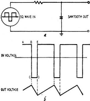
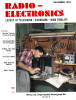
Fig. 1 - Generation of a sawtooth wave.
Fig. 2 - This kind of thing doesn't happen.
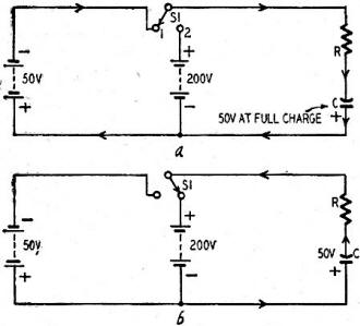
Fig. 3 - The capacitor is first charged to 50 volts, then is
discharged in series with a 200-volt battery, as shown.
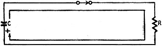
Fig. 4 - Simple R-C discharge circuit.
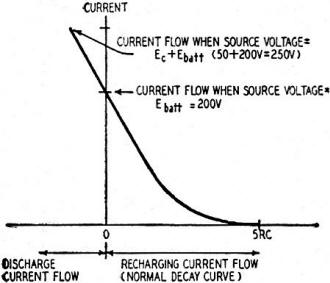
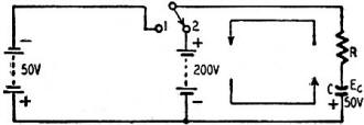
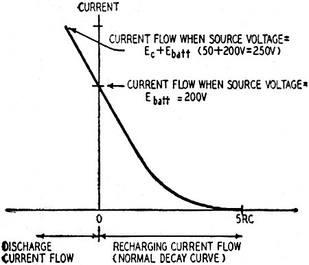
Fig. 5 - Current flow as capacitor discharges to 0, then recharges
to 200 volts.
By Cyrus Glickstein
The key to a circuit problem is often tied to one small point that just doesn't
fit into place. After the "minor" point is broken down, there is a completely new
picture of circuit operation. A simple illustration of this situation is shown in
the circuit of Fig. 1, where a sawtooth wave is projected from a square wave.
TV technicians are familiar with the fact that a square wave applied across an
R-C circuit as in Fig. 1-a, produces a sawtooth wave (Fig. 1-b) provided the R-C
circuit has a long time-constant and the output is taken off the capacitor (integrated).
It seems reasonable that the capacitor charges linearly when the square wave
is first applied, giving a rising saw-tooth voltage in the first quarter-cycle.
But in the next quarter-cycle, when the square wave voltage reverses, why doesn't
the capacitor voltage discharge exponentially to zero (as shown in Fig. 2) before
the capacitor charges up in the reverse direction? From ordinary R-C circuit theory
it seems a capacitor should do just that. Yet from experience (oscilloscope examination,
etc.) we know that a linear sawtooth is obtained.
This action is based on an interesting point about capacitor action not found
in most reference texts. The basic action can be illustrated in the circuit shown
in Fig. 3. The capacitor C has been charged to 50 volts on the No.1 position of
the switch, Fig. 3-a. When the switch is placed in the No.2 position (Fig. 3-b),
there is a 200-volt battery in series with the charged capacitor. In this switch
position, the capacitor first discharges to zero and then recharges in the opposite
direction to 200 volts. Current in the circuit then stops. How long does it take
the capacitor to discharge down to zero, before it starts charging in the reverse
direction? In a simple discharge circuit, Fig. 4, it takes a charged capacitor 5RC
to discharge to (approximately) zero. But the answer is definitely not 5RC in the
circuit of Fig. 3-b because this is not a simple discharge circuit. It is a modified
discharge circuit until the capacitor discharges to 0 volts. Then, the circuit acts
exactly like any normal charge circuit while the capacitor recharges in the opposite
direction to the battery voltage of 200.
To explain the discharge action, it must be remembered that in any R-C circuit,
whether charge or discharge, the current at the instant the switch is closed is
determined by the potentials in the circuit. These voltages may be in the battery
or across the charged capacitor or both, if the capacitor already has a charge across
it. In this case, at the instant the switch is thrown to the No.2 position, the
initial current depends on both the battery voltage (200) and the voltage across
the capacitor (50). The two voltages are in series and can be considered one voltage
in analyzing the action. An initial current flows which is based on the sum of the
two voltages. The discharge circuit therefore acts exactly the same as if the capacitor
were charged up to 250 volts, with no battery in the circuit. Current keeps decreasing
as the capacitor discharges to zero. At the instant the capacitor voltage is zero,
only the battery voltage of 200 is in circuit. The capacitor then charges in the
reverse direction. Current continues in the same direction and continues to decrease,
in typical charge circuit action. When the capacitor is fully charged to the battery
voltage, no current flows.
It does not take long for the capacitor to discharge to zero, compared to the
time needed for recharging. At the instant the switch is thrown to position 2, the
current is maximum. There is a voltage drop of 250 across R. When the capacitor
voltage is zero, there is a voltage of 200 (battery voltage) across R. Current therefore
must drop 20% or 1/5 to cause the voltage across R to go from 250 to 200 volts.
According to R-C series circuit theory, a 20% drop in current (or in voltage across
R or C) takes place in a time of 0.2 RC. More important, the first 20% of charge
or discharge in an R-C circuit is linear. To state this fact somewhat differently:
as long as the capacitor voltage is small (1/5 or less compared to the battery voltage)
when the switch is thrown to position 2, the discharge of the capacitor will be
linear. After the discharge to zero, the recharge in the opposite direction will
also be linear, provided the capacitor is not allowed to charge up to more than
20% of the source voltage.
Actually the initial discharge in such circuits can be considered a linear extension
of the standard charge curve for current (Fig. 5).
This principle explains the production of a sawtooth voltage across a capacitor
when a square wave is applied to an R-C circuit as shown in Fig. 1-a. Assume the
square wave (Fig. 1-b) is positive at A, when the switch is turned on. The capacitor
starts to charge. When the square wave goes sharply negative (B-C) there is no exponential
decay of voltage to zero before the capacitor recharges. Instead, the negative source
(square wave) voltage is in series with the voltage in the capacitor. It discharges
linearly to zero on the basis of the total voltage in the circuit. At the instant
the capacitor voltage reaches zero, it then starts to recharge in the opposite direction,
based only on the source voltage. The recharge is linear also, when the capacitor
does not have time enough to charge up to a substantial percentage of the applied
voltage. When the source voltage reverses polarity again, the capacitor voltage
again is in series with the applied voltage, and the discharge current is based
on the combined voltages. There is a linear discharge until the capacitor voltage
reaches zero, then it recharges, and so on.
A linear sawtooth is produced when the time-constant of the charging circuit
is large compared to the time of the applied voltage. The capacitor then charges
to only a small part of the applied voltage. This means it charges only on the initial
portion of the charging curve where the voltage rise is linear.
The principles of capacitor action discussed in this article can be applied to
clarify the operation, design, and repair of many different kinds of circuits.
Posted October 9, 2020
|