|
March 1953 Radio-Electronics
 [Table of Contents] [Table of Contents]
Wax nostalgic about and learn from the history of early electronics.
See articles from Radio-Electronics,
published 1930-1988. All copyrights hereby acknowledged.
|
Selecting the proper antenna
for a particular application can mean the difference between success and failure
when any combination of signal strength and/or signal interference is involved.
Modern spread spectrum technologies has eased the job a bit, but there are still
instances when high gain and/or directivity is necessary. You might be tempted to
say that gain and directivity are essentially the same thing, and to some extent
that is true. However, in the case of needing to minimize signal interference from
surrounding sources, a directional antenna might be utilized not due to a need for
increased desired signal strength but to reduce the power of undesired emitters.
Such was often the requirement for television and FM radio reception. After years
of needing to reorient the folded dipole antenna for my FM radio because of changes
in signal strengths of relatively nearby stations only a couple channels apart*,
I finally installed a
Channel Master antenna on an Alliance rotator mount. Now, when
changes in atmospheric and ground conductivity conditions cause adjacent channels
to bleed over into each other, I simply turn the dial on the rotator control and
voila, problem solved. Maybe a more selective FM receiver would help, but that would
take a pretty high-end (i.e., expensive) product. The same situation applies to
over-the-air TV broadcasts in the Erie, Pennsylvania, area, where a few degrees
difference in antenna pointing can stop the digital broadcasts from dropping out.
* 88.1 WEFR and 88.9 WSFE can interfere with 88.5 WMCE
Antenna Reference Chart
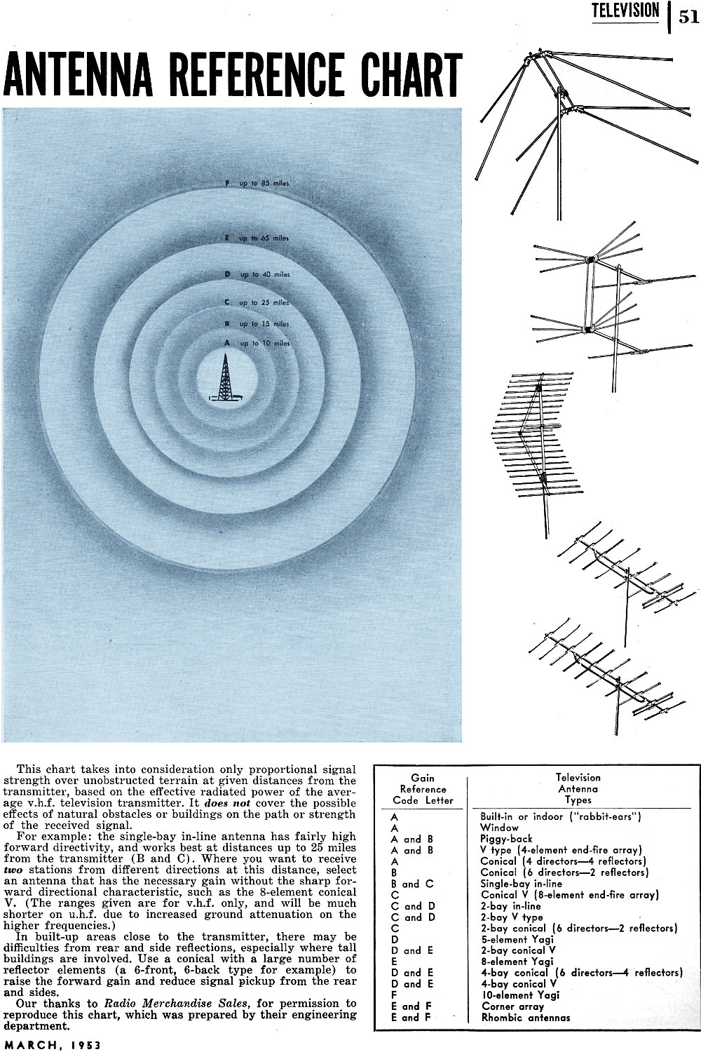
 This chart takes into consideration only
proportional signal strength over unobstructed terrain at given distances from the
transmitter, based on the effective radiated power of the average v.h.f. television
transmitter. It does not cover the possible effects of natural obstacles or buildings
on the path or strength of the received signal. This chart takes into consideration only
proportional signal strength over unobstructed terrain at given distances from the
transmitter, based on the effective radiated power of the average v.h.f. television
transmitter. It does not cover the possible effects of natural obstacles or buildings
on the path or strength of the received signal.
For example: The single-bay in-line antenna has fairly high forward directivity,
and works best at distances up to 25 miles from the transmitter (B and C). Where
you want to receive two stations from different directions at this distance, select
an antenna that has the necessary gain without the sharp forward directional characteristic,
such as the 8-element conical V. (The ranges given are for v.h.f. only, and will
be much shorter on u.h.f. due to increased ground attenuation on the higher frequencies.)
In built-up areas close to the transmitter, there may be difficulties from rear
and side reflections, especially where tall buildings are involved. Use a conical
with a large number of reflector elements (a 6-front, 6-back type for example) to
raise the forward gain and reduce signal pickup from the rear and sides.
Our thanks to Radio Merchandise Sales, for permission to reproduce this chart,
which was prepared by their engineering department.
Posted February 25, 2019
|