|
March 1954 Radio-Electronics
 [Table of Contents] [Table of Contents]
Wax nostalgic about and learn from the history of early electronics.
See articles from Radio-Electronics,
published 1930-1988. All copyrights hereby acknowledged.
|
 Often,
the photo on the covers of magazines is related to a feature article within, but
in the case of the March 1954 Radio-Electronics, only a couple
paragraphs are devoted to it. Although more commonplace back in the day, mention
of a Lecher wire for measuring VSWR values of the antenna under test caused me
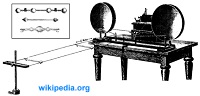
to look it up. The Wikipedia entry says, "Lecher line or Lecher wires
is a pair of parallel wires or rods that were used to measure the wavelength of
radio waves, mainly at VHF, UHF and microwave frequencies. They form a short
length of balanced transmission line (a resonant stub). When attached to a
source of radio-frequency power such as a radio transmitter, the radio waves
form standing waves along their length. By sliding a conductive bar that bridges
the two wires along their length, the length of the waves can be physically
measured. Austrian physicist Ernst Lecher, improving on techniques used by
Oliver Lodge and
Heinrich Hertz, developed this method of measuring wavelength
around 1888." Interesting, non? Often,
the photo on the covers of magazines is related to a feature article within, but
in the case of the March 1954 Radio-Electronics, only a couple
paragraphs are devoted to it. Although more commonplace back in the day, mention
of a Lecher wire for measuring VSWR values of the antenna under test caused me
to look it up. The Wikipedia entry says, "Lecher line or Lecher wires
is a pair of parallel wires or rods that were used to measure the wavelength of
radio waves, mainly at VHF, UHF and microwave frequencies. They form a short
length of balanced transmission line (a resonant stub). When attached to a
source of radio-frequency power such as a radio transmitter, the radio waves
form standing waves along their length. By sliding a conductive bar that bridges
the two wires along their length, the length of the waves can be physically
measured. Austrian physicist Ernst Lecher, improving on techniques used by
Oliver Lodge and
Heinrich Hertz, developed this method of measuring wavelength
around 1888." Interesting, non?
On the Cover: Antenna Testing Methods
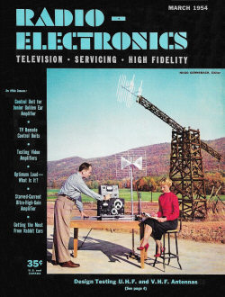 With the scenic Catskill mountains as a background, engineer Julius Green of
Channel Master, Ellenville, N. Y., is seen testing the Ultra-Bow antenna. With the scenic Catskill mountains as a background, engineer Julius Green of
Channel Master, Ellenville, N. Y., is seen testing the Ultra-Bow antenna.
The experiment in process consists of measuring the characteristic impedance
of the antenna. The girl, Barbara Watson, is recording standing-wave ratios as measured
on a Lecher wire and is taking signal generator and voltmeter readings.
The large wooden mast behind them is used for field testing. The tower mounted
on the mast can be pivoted in a vertical plane. The tower and mast represent the
receiving section of a transmit-receive setup.
At the end of the tower is mounted the antenna to be tested; in this case it
is the 2-bay Champion. The antenna can be rotated 360° by a selsyn motor mounted
on the tower and can be controlled from a nearby laboratory. The antenna under test
is rotated at a speed of 2 r.p.m. while the receiving pattern is automatically recorded.
Posted May 16, 2022
|