|
August 1969 Radio-Electronics
 [Table of Contents] [Table of Contents]
Wax nostalgic about and learn from the history of early electronics.
See articles from Radio-Electronics,
published 1930-1988. All copyrights hereby acknowledged.
|
  You might have heard of Pixie tubes and Nixie
tubes from the era preceding light emitting diodes (LED's), but how about Elfin
tubes? They were considered the next stage in the evolution of digital display devices.
This article from a 1969 issue of Radio-Electronics magazine provides an
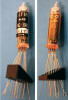
introduction to Elfin tubes. The images above are from a listing on eBay (at this time) offering to sell
MG-19B Elfin Readout tubes for $10 each, in case you want one for a conversation
piece or for a project. Elfin tubes are fairly accessible if this guy depletes his
supply. I grabbed a shot of the tube and datasheet in case they disappear someday. You might have heard of Pixie tubes and Nixie
tubes from the era preceding light emitting diodes (LED's), but how about Elfin
tubes? They were considered the next stage in the evolution of digital display devices.
This article from a 1969 issue of Radio-Electronics magazine provides an
introduction to Elfin tubes. The images above are from a listing on eBay (at this time) offering to sell
MG-19B Elfin Readout tubes for $10 each, in case you want one for a conversation
piece or for a project. Elfin tubes are fairly accessible if this guy depletes his
supply. I grabbed a shot of the tube and datasheet in case they disappear someday.
Experiment with Digital Readouts
 By Jim Ashe By Jim Ashe
New miniature indicator lamp displays both letters and numbers. Circuits show
you how to get crisp, brilliant alphanumeric readouts
The race continues. Both solid-state and neon-glow alphanumeric indicators have
their special advantages, but now the neons are corning on strongly in the form
of some new subminiature indicators.
Aleo Electronic Products Inc. (Lawrence, Mass.) recently introduced MG-19 Elfin
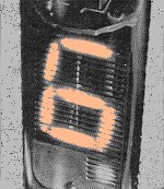
indicators for small instrument work. Their crisp, bright red-orange images are
adequate in almost any illumination.
How Elfins Work
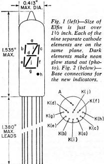
Fig. 1 (left) - Size of Elfin is just over 1 1/2 inch. Each
of the nine separate cathode elements are on the same plane. Dark elements make
neon glow stand out.
Fig. 2 (right) - Base connections for the new indicators.
The new indicators are tiny but complex cold-cathode neon lamps. Unlike other
similar devices, they offer a single-plane display composed of nine segments (Fig. 1).
Depending on your needs, a fairly complex circuit may be required to decode a binary-coded
decimal or other signal. But Elfin indicators can display many alphabetic as well
as all numeric characters.
Each Elfin indicator bulb has 10 electrical connections (Fig. 2). Lead A
is the common anode, and the other nine leads go to the segments shown in Fig. 1.
If the anode is connected to about +200 volts and the cathode leads are grounded
through a 220,000-ohm resistor, the segments will glow. The decimal point, a smaller
element, requires a series resistor several times larger.
Electrically, the Elfin is merely a glorified neon lamp. However, its turn-on
and turn-off voltages are considerably higher than ordinary neon lamps, perhaps
as a result of a special gas mix for its "prolonged life span" specification. The
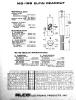
manufacturer's specs appear in Table I. Notice the lower current for the decimal
point.
The brightness of these little in-dicators is quite surprising. This is partly
due to the light-absorbent quality of the electrical elements, which provides a
dark background area even when the Elfin is unmounted. But the neon glow is very
bright in itself. Manufacturer's specs suggest 1 mA cathode current is not excessive,
and tests at this level gave a brightness suitable for any ambient lighting short
of direct sunlight. For longer life, the Elfins operate at several tens of microamps
per cathode, but brightness is considerably reduced.
The operating curve I ran (Fig. 3) is provisional, since specified operating
voltages are higher than those I obtained by testing preproduction samples I used.
This graph shows what we expect: for a given current there's a definite voltage
across the lamp, and the voltage increases as the current rises in the usual operating
range. Since neon lamps show a very sharp current-voltage dependence, we get this
curve by varying the overall voltage through a large series resistor. I adjusted
the current to 0.5, 1.0, and 1.5 mA, measured the voltage across the elements at
each setting and checked at 0.2 mA for the decimal point. There was some variation
between elements and from one tube to another.
Some Basic Circuits
Although Elfin firing and operating voltages look like something from a history
book, it's not hard to generate adequate voltages at the required low currents.
A gas regulator tube or two can provide stabilization. Since a voltage-regulator
tube can handle up to 25 or 30 mA of output current, we can easily operate at least
six Elfins at fairly high current levels.
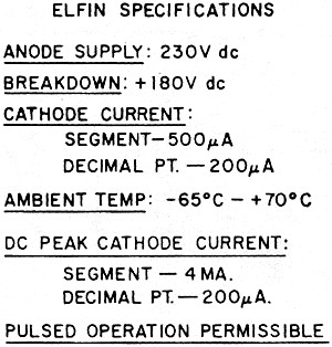
Table I - Elfin Specifications
Elfins are excellent for nearby or remote indication of switch position, servo
function and other jobs where the control system consists of a switch assembly,
a power supply and perhaps a lot of wire. With the diagram in Fig. 4 you can
work out your own design for this purpose.
Here, each Elfin cathode element has a series current-limiting resistor, with
the dot element (if used) having a larger resistor since it requires less current.
A single resistor is not used in the anode element, as with Nixie tubes, because
as different configurations of lighted elements are selected the total anode current
varies. This simple switching system requires no diodes or other semiconductors.
Simply wire the fixed contacts so all the appropriate elements are connected to
ground for each switch position.
In this arrangement a separate switch wafer for each element is necessary. That
works out to a seven- or a nine-wafer switch, and one posi-tion per character to
be displayed. With diodes this complexity can be reduced to a single-wafer switch
(see Fig. 5).
In position 1, only cathode Ka sees an electrical connection to ground.
In position 2, only cathode Kb fires, in position 3 they both fire and
so on. Design this system to your specs by choosing a given switch position and
marking each intersection for the input line to the appropriate cathode. During
assembly, wire a diode around each marked intersection.
If you don't understand what the diodes do, imagine one replaced by a piece of
wire, and then run the switch through its positions. This is simply a diode matrix,
requiring 49 diodes to read out the integers 0-9 from a single-pole 10-position
switch. Power diodes rated at 200 PIV can be used in the matrix, rather than the
more expensive signal diodes.
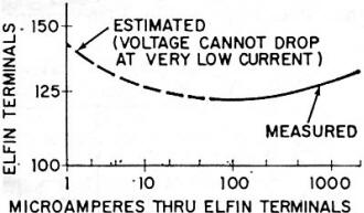
Fig. 3 - Voltage-current characteristics measured from three
preproduction Elfins.
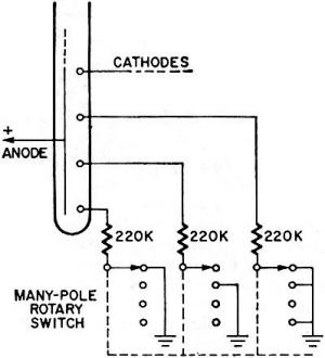
Fig. 4 - Driving the Elfin from a multiple-wafer switch,
at one wafer for each cathode.
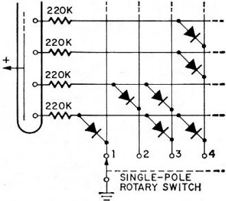
Fig. 5 - Diode matrix arrangement permits use of single-pole
switch to light tubes.
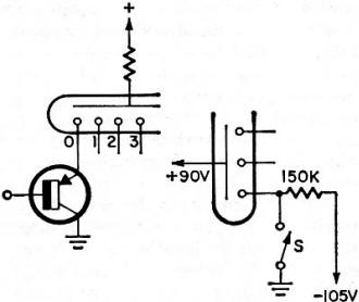
Fig. 6 (left) - Transistor switching arrangement possible
with low-voltage Nixie tubes.
Fig. 7 (right)- Firing voltage and typical setup to operate
Elfins.
How about Elfin indicator control with solid-state switches? Nixies are sometimes
controlled directly by the circuit shown in Fig. 6, but transistors for this
application would need 200-volt VCEO ratings. A catalog disclosed no
possibilities of the small-signal, inexpensive variety. We will have to try strategy,
and the answer appears back in Fig. 3, the measured EI curve.
By switching the Elfin between some off state of insufficient voltage to some
on state of adequate current, the voltage swing can be low enough to be handled
by ordinary transistors .. A workable scheme appears in Fig. 7.
It works this way. Suppose switch S is closed. We have +90 volts from supply
to ground through the switch. (If you feel uncomfortable about that, you're thinking
about ordinary neon indicators that would be destroyed in this circuit.) Our measured
EI characteristic shows there's no current flow with 90 volts applied. There will
be about 0.8 mA flowing from ground to the minus supply. Then switch S is opened.
This gives us the sum of the positive and negative supply voltages applied to
the Elfin indicator through at 150,000-ohm resistor. The Elfin fires, and the supply
voltage goes to about 120 volts across the indicator, about 80 volts across the
resistor, and perhaps 0.5 mA flowing. The upper switch contact falls from zero volts
to -30 volts, acceptable to an ordinary transistor. We see this requires a pnp transistor.
Now let's do this with transistors. The complete indicator circuit appears in
Fig. 8. Here, a bias resistor from base to minus holds each pnp transistor
saturated until a turnoff signal is applied. This signal switches the transistor
off, and its Elfin element lights up. Diodes D1, etc. prevent excessive transistor-base
turnoff voltages, and may be omitted in many designs of known drive and transistor
ratings.
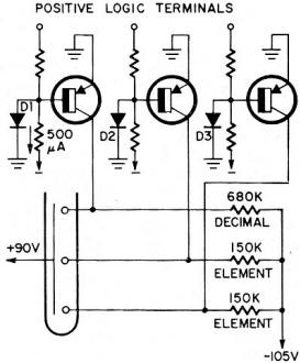
Fig. 8 - Transistor circuit for controlling Elfins. High
VCE is not needed, since transistors are clamped.
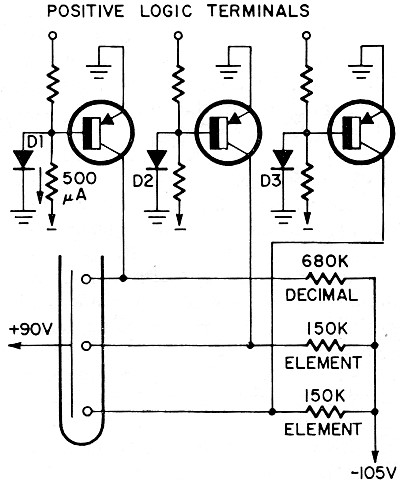
This circuit is controlled by positive logic, and since the transistor base terminals
are clamped only a few hundred millivolts negative, we can easily use conventional
positive-supply, positive-logic IC's. Now, if you want to drive the indicator from
a parallel line at one lead per character, you can use the matrix idea previously
mentioned to translate from character logic to element logic.
There are now lots of appropriate transistors. Since the VCEO rating
is a pessimistic one established under open-base connections, a 25-volt rating may
be adequate. I'd choose at least 30 volts, and General Electric's 2N5365 transistor,
prices at 55¢, is rated at VCEO = 40 volts.
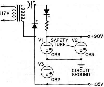
Fig. 9 shows a simple power supply circuit. If later samples of the fins
turn out to have higher operating voltages than my preproduction samples, simply
choose higher-voltage regulator tubes and review the design.
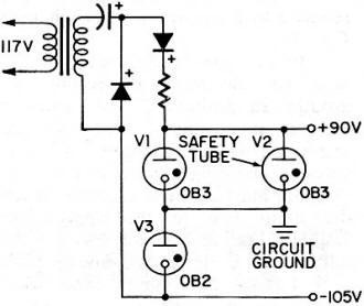
Fig. 9 - Power supply for indicators can use extra VR tube
for safety.
What if regulator V1 fails? That would overvolt the Elfins in turnoff, and we
could expect a disastrous failure costing us an Elfin and many transistors per integer
displayed. The answer is simple: simply add another similar tube in parallel with
V1 and mark on the chassis which tube should fire in normal operation. If you check
one day and the wrong tube is lit, your safety factor has diminished but is easily
restored by a new VR tube.
Posted August 1, 2024
(updated from original post
on 8/1/2018)
|