|
March 1969 Radio-Electronics
 [Table of Contents] [Table of Contents]
Wax nostalgic about and learn from the history of early electronics.
See articles from Radio-Electronics,
published 1930-1988. All copyrights hereby acknowledged.
|
Maybe it is because I recently
rebuilt a set of stereo speakers that this article on frequency crossover circuits
seemed appropriate for posting. Crossovers networks are essentially an audio version
of a an RF multiplexer filter. The speakers were just some cheap jobs from an old
system where one had a split in the 8" bass speaker cone. I wanted to keep the
enclosures since they match the receiver and turntable and replace just the speakers
themselves. The so-called crossover circuit consisted of a series capacitor in one
line of each of the midrange and tweeter speakers (I told you it was cheap). Good
quality stereo speakers and a good crossover circuit would have cost a couple hundred
dollars - well beyond my budget, so I opted for some just-above-low-end car speakers. The speaker with a built-in
2-way crossover has a frequency response of 30 Hz to 15 kHz and the 3-way speaker
goes from 50 Hz to 22 kHz. Home stereo speakers are typically 8 ohms whereas
car speakers are typically 4 ohms, so I just wired them in series. Since the stereo only
puts out about 10 watts per channel, I'm not too concerned about distortion (good enough
for my 60-year-old ears). Although it is kind of embarrassing to admit to owning as my
only stereo, here is a little info about the
Reader's
Digest Model 800-XR AM/FM Radio + 8-Track Tape Player system.
Crossovers, Electrical or Electronic?
Crossover Showdown
by Norman H. Crowhurst
This question isn't easy to answer. The question isn't as easy as a question ought
to be, because what's on the questioner's mind may not coincide with what the answerer
thinks he's answering. How's that?
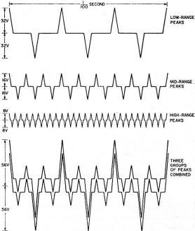
Fig. 1 - Stylized representation of signal peaks in a three-way system.
You can see how the total peak power required is more than double the sum of the individual
peak powers required.
Really, here are several questions, wrapped up together, and to answer them properly,
we must separate them. What most people probably think of is whether the frequency separation,
associated with crossovers, should be performed before or after power amplification.
Label that question 1.
Then there's the matter of whether the correct overall power level is maintained throughout
the frequency response, and which form achieves the more successful separation, as far
as distortion-free performance is concerned. That's a more involved question, but we'll
label it question 2, for the time being.
Before Or After Power Amplification?
The big reason for using multi-way speakers, which creates the need for crossovers,
is avoiding intermodulation between frequencies in different parts of the audio spectrum.
Intermodulation comes in two major forms: 1. Lower-frequencies combined with higher frequencies
can modulate the latter, creating a gargly effect. 2. More than one higher frequency
may intermodulate, between themselves, creating a buzz at the difference frequency, which
is lower.
Keeping the segments of the audio spectrum separate avoids the gargly effect, because
the high frequencies go to a different unit, and thus aren't modulated by the lower frequency.
It also avoids the buzz effect, because the higher frequencies are reproduced in a unit
that won't reproduce the lower-frequency buzz generated between them.
But really, one big power amplifier is better than two or three smaller ones, isn't
it? Not necessarily.
Let's say we have a three-way system, where the bass unit may handle 32 watts, the
mid-range 8 watts and the tweeter 2 watts. All are 16-ohm impedance units. One argument
suggests that power never comes to all the units at the same instant, so a 35-watt amplifier
should suffice.
The more usual notion would add up 32 + 8 + 2, which makes 42 watts, and we conclude
that a 50-watt amplifier should be plenty big enough.
Let's consider a simplified signal containing peak signals in each range, of maximum
amplitude for that range. Power ratings are based on the average power in a single sine
wave. So peak power is twice the rated value. Waveforms add, whether they're sine waves
or more complicated musical compositions.
A peak power of 64 watts at 16 ohms calculates to 32 volts peak. A peak power of 16
watts at 16 ohms is 16 volts peak. And 4 watts peak at 16 ohms is 8 volts peak. If one
amplifier handles all three, there will be points where all three waveform peaks will
momentarily add, although on average, they won't.
For example, if the frequencies at which peaks occur are 300, 900 and 2,700 respectively,
then 3 times every 0.01 second (10 msec) in each polarity, the three waveforms will momentarily
add. For the rest of the time, they won't (Fig. 1).
But 3 times each 10 msec, the amplifier must handle the equivalent of 32 + 16 + 8
volts peak (not watts). So to handle the peaks at these moments, the amplifier must be
capable of handling 56 volts peak, which represents 196 watts peak, or a rating of 98
watts.
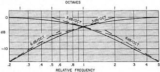
Fig. 2 - Frequency response of simple RC (series and shunt) rolloffs,
when they are used as crossovers.
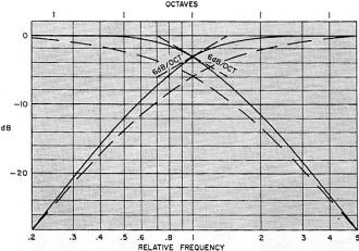
Fig. 3 - Correct 12-dB/octave response (solid-line curves) and the
effect of combining two 6-dB/octave responses (shown as dashed-line curves).
This is more than double the sum of the individual powers, which was 42 watts. If
you use separate amplifiers, they could be rated at 32, 8 and 2 watts, respectively,
quite satisfactorily. But if you use a single one, it must be rated at 98 watts to handle
the same overall signal. That's quite a difference. What it amounts to is that those
three smaller amplifiers can produce as much total sound as a single 100-watt amplifier
handling the whole signal.
This additive effect aggravates the intermodulation problem. Even though the single
amplifier may be relatively free of intermodulation distortion at its lower levels, any
amplifier produces large slices of distortion, both harmonic and intermodulation, any
time its peaks run into overload.
So choosing a 50-watt amplifier, based on merely adding the separate powers required,
means that the momentary 200-watt peaks, that should have a 100-watt amplifier to handle
them, will produce a large amount of intermodulation distortion, concentrated in those
short moments, 3 times every 10 msec in the illustration used.
Here is another disadvantage. Suppose you do use a 100-watt amplifier, to be sure
you have the peak power available. Now you have an average power of 100 watts available,
too. If the system is turned up too high in level, all the units can receive twice the
power for which they are rated. Or one of them could sometimes get the full 100 watts,
which is even worse. This definitely endangers the units: they could be damaged or burned
out.
So trying to make a single power amplifier feed a multiway system really puts us between
the devil and the deep blue sea. That pretty well answers the before-or-after power amplification
question. Now we come to the more involved question.
How Steep the Rolloff?
This has always been a question, even before electronic crossovers came into the picture.
Really it relates to certain qualities about loudspeaker unit frequency response. Speakers
for use in a multiway system are designed to handle their own frequencies well, but should
not be given frequencies outside their own range.
The basic RC rolloff (Fig. 2) produces a 6-dB/octave ultimate slope. At the crossover
frequency, each output receives half-power, or is 3 dB down, and the slope is 3 dB/octave.
An octave one side or the other of crossover frequency, one unit is 1 dB down and the
other is 7 dB down; not a big differential, nor is it rapidly made.
The better speaker units will work with only such 6-dB/octave crossovers. But some
should really have at least 12-dB/octave crossovers. This response is not just the 6-dB/octave
response doubled (Fig. 3). If it was, the method would be simple: just use two of them.
A better way to view the 12-dB/octave response is as the simple response squeezed into
half the frequency range (on a log scale).
Thus we could tabulate the difference between the responses in this way:
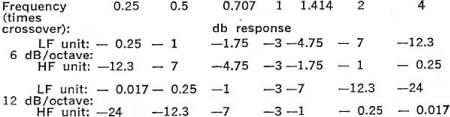
If you put together two 6-dB/octave networks, the attenuation at crossover will be
6 dB, and the total power from the two units is -3 dB at this frequency. There is a dip
in the overall response, and the slope doesn't change much more rapidly than the single
unit.
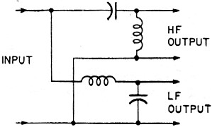
Fig. 4 - Circuit for electrical crossover filter. Each element has
a reactance of 1.414 times the terminating impedance, at crossover frequency. When correctly
terminated, it yields the true 12-dB/octave response.
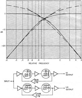
Fig. 5 - Getting correct 12-dB/octave response with feedback. Dashed-line
curves indicate response before feedback is applied. The block diagram indicates the
essentials of this method.
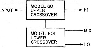
Fig. 6 - How to use two CM Laboratories model 601 electronic crossovers
to set up a three-way system.
The only way to get a correct 12-dB/octave rolloff is either to use the correct electrical
circuit (Fig. 4) feeding the loudspeaker units direct, thus putting the crossover after
power amplification, or to use the RC stages with feedback to provide the equivalent
interaction (Fig. 5).
A number of manufacturers, aware of the advantage of separating the frequencies before
the power amplification, have advertised electronic crossovers. An incidental advantage
to manufacturers is that it sells more power amplifiers! But up to date no commercial
equipment has been made available that produces the correct response for 12-dB/octave
(or steeper) rolloffs.
I have written articles giving design data from which one can be built (item 5 below),
but to date they have not been made commercially available.
However, one quite useful unit has recently made the scene. In performance, it does
no better than a simple RC crossover, yielding 6 dB/octave. But it does provide considerably
greater flexibility in use than any simple RC network could.
This is the C-M Labs Model 601 Electronic Crossover. Its advantage over simple circuits
is that it has seven "element" frequencies for the crossover: 100, 200, 400, 800, 1,600
3,200 and 6,400 Hz. These are selected by slide switches. Thus 2,000 Hz can be made up
as 1600 + 400, or 3,500 Hz as 3,200 + 200 + 100.
With this arrangement, 127 crossover frequencies are possible, at 100-Hz intervals
from 100 to 12,700 Hz.
The electronic circuits are used to provide isolation between elements, and freedom
from distortion over this wide range of control. The unit has zero voltage gain (output
same level as input) using an input of 100,000 ohms and an output for connecting to 10,000
ohms or higher, from a 600-ohm source. It has a level control for each output. The units
may be cascaded to achieve three-way crossover (Fig. 6).
Making a 12-dB/octave network involves applying some 6 dB of negative feedback (minimum)
around two RC rolloffs in cascade. As the feedback will be different from each output,
the input needs buffering, so the feedback affects only the channel over which it is
applied.
Input and output should be buffered so that impedance termination does not radically
affect response. Modifying the feedback and roll off points, and adding further rolloffs
without feedback, can synthesize 18-dB/octave crossovers, but responses this .sharp are
apt to spoil transient performance.
A good choice rests between the 6 dB/octave, which the C-M Labs Model 601 provides
in great variety, or 12 dB/octave, which you'd have to make up for yourself at the moment.
In another article, I'll give data and details of aligning the circuit to obtain correct
response for a transistorized version.
Bibliography
1. Norman H. Crowhurst, "Loudspeaker Crossover Design;" Radio-Electronics, July 1952
2. Norman H. Crowhurst, "More About Filters," Radio-Electronics, April-May 1953
3. Norman H. Crowhurst, "Questions about Crossovers," Radio-Electronics, July-August
1956
4. Herbert Ravenswood, "Electronic Dividing Networks," Radio-Electronics, September
1957
5. Norman H. Crowhurst, "Multi-Channel Electronic Crossovers," Radio-Electronics,
December 1957
*Radio-Electronics, December 1957, contained one such article.
Posted August 21, 2018
|


