|
November 1968 Radio-Electronics
 [Table of Contents] [Table of Contents]
Wax nostalgic about and learn from the history of early electronics.
See articles from Radio-Electronics,
published 1930-1988. All copyrights hereby acknowledged.
|
University of Southampton,
England, professor James Holbrook suggests in this 1968 Radio-Electronics magazine
article an "easy-to-follow substitute for the left- and right-hand rules," but I'm
not so sure that the good professor's "Electron Orbit Method" is any better or easier
to remember. Admittedly, it is hard to remember whether the use a left-hand rule
or a right-hand rule for the various physical laws - motor rotation direction, current
induction, torque, vector cross products, etc. Those involving current flow are
made even more confounding because you need to know whether the creator of the rule
refers to
conventional current flow (positive-to-negative) or
electron current flow (negative-to-positive). Note in
Figure 110 from the Electricity volume of Basic Navy
Training Courses how the generator rule is described as a left-hand rule with conventional
current flow. However, the modern version for electron current flow uses a
right-hand
rule (Fleming) for the same thing. Your best option is to look it up
from a reliable source when the need arises.
Electrons and Magnetic Fields
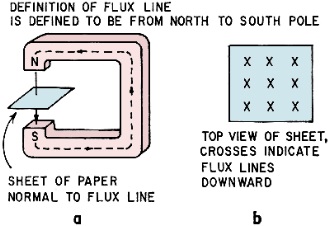
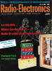
Fig. 1a - Magnetic flux lines are arbitrarily defined as
being from North to South poles of a magnet; (b) crosses represent field directed
from above into page.
An expert describes an easy-to-follow substitute for the left- and right-hand
rules.
By James G. Holbrook *
Basic electricity and magnetism theory often seems dull and dry. We're impatient
to hurry on to things more practical and interesting, and consequently we often
continue to learn electronics while still uncertain about elementary principles.
I've selected a few short problems which are useful to detect any uncertainty
you may have about electronic motions in magnetic fields. Several of these questions
have made research engineers and physicists reconsider basic theory.
Fig. 1-a shows the arbitrary but standard definition of the direction of
magnetic flux lines as being from the North to the South pole of a magnet. Fig. 1-b
thus implies there is a North pole somewhere above the page, with the crosses indicating
flux directed into the page.
Fig. 2-a - What is polarity of terminals touching rim and
shaft of Faraday disk generator rotating in uniform magnetic field? b - With magnets
fixed as shown, will light spot deflect to a, b, c or d?
Stop! Before reading further, examine the two problems in Fig. 2. Part (a)
is a Faraday disk generator, showing a conducting disk rotating clockwise on its
axis, and with a uniform magnetic field into the page. The disk is of nonmagnetic
material, and thus the field is uniform through, as well as around, the disk edges.
Brushes touch the center and outer rim of the disk. and motion of the conducting
disk in the field causes a voltage to appear at the terminals.
The problem is which terminal is positive and which is negative. Make a definite
choice and don't change; there are of course only two possibilities. Use any method.
Next, look at part (b) which shows the face of a cathode-ray tube with the beam
normally striking the exact center of the screen. However, with two magnets around
the neck will the beam be deflected to position a, b, c or d? Again make a definite
choice.
If you were uncertain about your answers, you will probably find the following
new concepts interesting.
First, make a clean break with the traditional left- or right-hand rules. just
as many have done with the idea of an external current from positive to negative.
Second, consider a new Electron Orbit Rule:
When an unrestrained electron moves in a plane normal to a magnetic field. it
will circle clockwise when the field is directed away from the observer.
This new rule is illustrated in Fig. 3. Part (a) shows the field directed
away from the observer, and the electron, upon entering normal to the field, begins
to circle clockwise. Part (b) shows a symbol which may be used to remember the rule:
One flux line into the page, and the orbit or path of one electron. The following
applications show how this concept is applied. This is called the "Electron Orbit
Method."
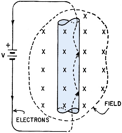
In Fig. 4 an enlarged view of a conductor is shown at rest in a magnetic
field. Connecting wires to an external battery will cause a current of electrons
to move from the negative terminal into the region of the field. But the Electron
Orbit Rule says the electron must circle clockwise, thus it strikes the inside of
the wire-to-air boundary (shown by the dotted line), and exerts a force to the right
of the wire.
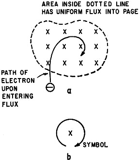
Fig. 3-a - Electron circles clockwise when entering field
directed away from observer. b - Electron Orbit Rule symbol.
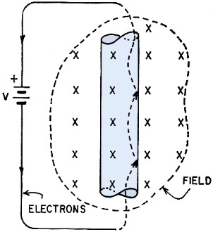
Fig. 4 - Motor action is illustrated by electrons striking
right hand boundary of conductor, forcing wire toward the right.
This particular electron is now at rest. It immediately begins to move again,
however, because of the attraction from the positive end of the battery. As soon
as it gets up speed, it again circles clockwise in accordance with the rule, striking
the wall. This boundary is very real, as the electron is free to move inside the
wire, but strikes a solid wall at the boundary and cannot get through unless the
wire is heated to emission temperature, as in a cathode.
You might wonder how a small electron could exert much force upon striking the
inside boundary. But remember there are 6.28 X 10¹⁸ electrons passing
a given point on the wall each second for each ampere of current, and the combined
effect is to move the wire.
A wire is shown at rest in Fig. 5-a. No connections are made to the ends.
This wire is uncharged, and therefore its free electrons are uniformly distributed
up and down the wire. One free electron is shown at the center. We again have a
field into the page.
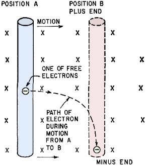
Fig. 5 - Generator action is shown as wire is pulled from
position (a) to position (b) and electrons move to lower end of wire.
If this wire is physically pulled to the right (not rotated), the electron, being
inside the wire, is pulled along with it to the right. But the Electron Orbit Rule
says the electron moves clockwise. Hence the electron in the wire follows the clockwise
dotted line as the wire moves to position (b). Of course all the free electrons
behave in the same way, and the bottom of the wire becomes highly negative. The
wire must be kept in motion, or the electrons will merely uniformly redistribute
themselves.
The problem in Fig. 2 should now be simple. In part (a) choose any electron
at rest in the disk, then start rotating the disk. This first starts the electron
in a line normal to the radius. But once moving, it must, by our rule, circle clockwise
(toward the axis) and thus the center of the disk, or the lower terminal, is negative.
In part (b), the field is directed downward to the right, and when viewed from
alongside the South pole of the upper magnet goes through the glass away from us.
The electrons are then rushing into the field from our left and circle clockwise,
striking the screen at "c."
With a little practice you can easily re-orient fields and electron orbits to
any position. Try applying the new rule to a one-turn loop passing through a field.
Remember, it really makes no difference whether the field moves toward the electron
or the electron moves toward the field.
The technique will show what sort of potential difference appears on opposite
sides of a wire in a field as current passes (the Hall effect in physics), and polarities
of voltage induced in transformer secondaries, etc. New applications and even new
ideas in electronics will occur as you become familiar with the interaction of electrons
and magnetic fields.
* Research Fellow,
University of Southampton, England
Posted May 31, 2023
(updated from original post
on 11/29/2018)
|