|
December 1958 Radio-Electronics
 [Table of Contents] [Table of Contents]
Wax nostalgic about and learn from the history of early electronics.
See articles from Radio-Electronics,
published 1930-1988. All copyrights hereby acknowledged.
|
I have to admit to not
being real certain why I selected this article on feedback tone control for posting.
It appeared in the December 1958 issue of Hugo Gernsback's Radio-Electronics
magazine.
Although it is a good write-up on some simple audio frequency filtering circuits,
and the principles can be applied to any frequency, it is most likely this page
was marked because it contained an
electronic-themed
comic on it. Oh well, Melanie already scanned and OCRed it for me, so you might
as well go ahead and read it.
Feedback Tone Control
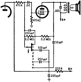
Fig. 1 - Circuit of the 4-position feed-back tone-control circuit.
By A. V. J. Martin
High-fidelity tone controls through feedback
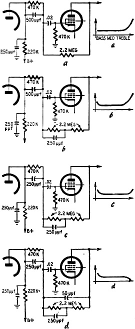
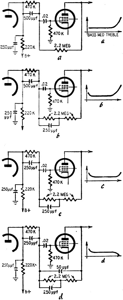
Fig. 2 - Feedback circuits for each switch position of Fig. 1 and their
effect on frequency response: a - treble boost; b - bass and treble boost; c - same
as b, but treble boost starts at higher frequency; d - bass boost and treble cut.
This elaborate tone control using a separate feedback chains found in some Marquett
French receivers. The theoretical circuit is shown in Fig. 1. The af voltage
from the anode of the preamp is applied to the grid of the power amplifier through
a divider made of two 470,000-ohm resistors. The grid thus receives only half of
the af voltage. However, a low-value capacitor is connected in parallel with the
first 470,000-ohm resistor, effectively short-circuiting it at high frequencies
and producing an important treble boost.
This arrangement is completed by a feedback chain around the power stage. A four-position
switch modifies the effect of feedback. To make things clearer, the simplified diagrams
Figs. 2-a, -b, -c, -d, show what is the actual circuit for positions 1 to 4 of the
switch.
In position 1 (Fig. 2-a), the feedback chain is a simple 2.2-megohm resistor,
giving an overall feedback ratio of the order of 10%. The high frequencies are boosted
by the coupling circuit so that this is a treble-boost circuit.
In position 2 (Fig. 2-b), a series R-C combination appears in the feedback
path. It reduces by approximately 50% the feedback at low frequencies, which becomes
5%. At medium frequencies, you obtain the full 10% feedback. At high frequencies,
there is the boost due to the coupling circuit. This is then a bass- and treble-boost
circuit.
In position 3 (Fig. 2-c), the circuit is identical with Fig. 2-b, except
for the fact that the shunt capacitor in the coupling circuit now has the lower
value of 250 μμf. The treble boost appears at higher frequencies. The bass
and medium frequencies behave as in Fig. 2-b. This then is again a bass-and-treble-boost
position, the treble boost coming into play for the higher frequencies.
In position 4 (Fig. 2-d), the circuit differs from Fig. 2-c by the
connection of a 50-μμf capacitor between plate and grid of the power stage.
This causes a strong feedback at high frequencies, but does not modify the behavior
of the circuit for bass and medium frequencies. This is then a bass-boost-treble-cut
circuit.
The simplified response curves included in the diagrams give a rough idea of
the effects of this clever circuitry.
Posted June 30, 2022
(updated from original post on
1/6/2015)
|