|
June 1969 Radio-Electronics
 [Table of Contents] [Table of Contents]
Wax nostalgic about and learn from the history of early electronics.
See articles from Radio-Electronics,
published 1930-1988. All copyrights hereby acknowledged.
|
A 720-line HDTV display is made
up of 1,280 vertical lines and 720 horizontal lines of pixels, which gives a total of
921,600 pixels. A 1080-line HDTV has 1,920 vertical lines and 1,080 horizontal lines,
for a total of 2,073,600 pixels. In 1969, a 230 vertical line by 230 horizontal line
electroluminescent (EL) flat-screen television display with 52,900 pseudo-pixels was
considered a big deal - and it was since it was the starting point for digital flat-screens
of today. Interestingly, while the "pixel" distribution was square, the actual display
retained the standard 4:3 aspect ratio, meaning horizontal element width was 33% greater
than the vertical element. Since each EL element was addressed individually, there was
no ability of a picture element to be shared by adjacent "pixels," so displaying a circle
would result in a very pixelated picture. A standard
cathode ray
tube (CRT), while having 525 vertical lines of phosphor "dots," it had effectively
an infinite number of horizontal lines since the video intensity signal was analog. The
CRT's electron gun, during its sweep, could simultaneously illuminate adjacent phosphor
dots, giving a smoothing effect that could render a true circle - even though under close
inspection it had a fuzzy edge. BTW, an
iPhone 8 Plus
display has 1080 x 1920 pixels (same as 1080p HDTV) for a total of 2,073,600 pixels.
A Galaxy
S8 has 1440 x 2960 pixels (same as 1440p HDTV) for a total of 4,262,400 pixels.
Flat-Screen TV Has 52,900 Picture Elements
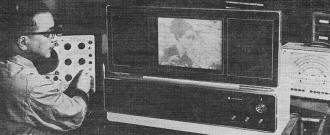
Experimental flat-screen set is checked by project director Yoshiyama.
Model uses some 8,600 components.
New York - Curious visitors jammed the darkened interior of Panasonic's booth at the
March IEEE Show to view TV programs on a screen no thicker than this magazine. The 50-pound
experimental set is likely to be a forerunner of flat-screen models that can be hung
on walls.
The 8.0 x 10.7 - inch electroluminescent screen has 230 vertical and 230 horizontal
electrode strips. A phosphor layer between these strips (diagram, right) provides 52,900
picture elements. The 0.04 x 0.03-inch size of each element maintains the standard 4:3
picture ratio.
Resolution is fair, but the phosphor has a distinct green hue and contrast and brightness
are low. Writing in Electronics, project director Masami Yoshiyama compares the image
detail to that obtained from some low-cost video tape recorders. Instead of the odd-even
scan pattern used in conventional receivers, both fields are successively displayed on
the same horizontal lines. This boosts brightness but cuts resolution.
Lumped Video Delay

Screen photo made during IEEE show. Image is a dark green color.
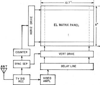
Electroluminescent (EL) flat panel.
Here is how a single horizontal line of the 230 x 230 matrix is scanned. The horizontal
electrode receives a negative selecting pulse, while blanking pulses dim the lines not
being scanned. Simultaneously, a sampled video signal for the entire line is applied
to all the vertical electrodes. This is accomplished with a 50.6-μsec lumped delay line,
which holds the video for the scan line until it can be displayed simultaneously when
the horizontal pulse is applied.
The brightness of each element is a function of the video pulse amplitude on the vertical
strips, varying exponentially, within limits, with the pulse width. The input transistor
to each vertical strip serves as a variable resistor, its collector resistance modulated
by the sampled video from the delay line.
Then, after one line has been scanned, a counter, triggered by the horizontal sync
signal, steps the horizontal pulse distributor to the next line. A second horizontal
pulse generator simultaneously delivers blanking pulses to all other lines.
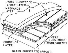
Improved Phosphor
The cutaway drawing of the matrix display panel shows an impedance layer between the
horizontal electrodes and the phosphor layer. This reflective coating of barium titanate
improves brightness and contrast because of its nonlinear characteristics. The vertical
strips are transparent, and the horizontal electrodes are aluminum evaporated.
Panasonic plans to test a display panel with an improved phosphor coating shortly.
The zinc sulphide compound used now requires dim lighting for comfortable viewing.
The prototype model demonstrated at the Show was equipped with provisions for video
tape recorders and closed-circuit cameras in addition to VHF reception. With circuit
modifications, the display system could be adapted for graphic and alphanumeric readouts.
IC's are used in the counter circuits and could simplify the brightness circuits.
Some 8,600 components are used in the set, comparable to the number in a desk-top
electronic calculator. Power consumption is about 100 watts.
Posted July 25, 2018
|


