|
October 1952 Radio-Electronics
 [Table of Contents] [Table of Contents]
Wax nostalgic about and learn from the history of early electronics.
See articles from Radio-Electronics,
published 1930-1988. All copyrights hereby acknowledged.
|
You're not going to
find much information about the "Futuramic" antenna by doing an Internet search.
I had never head of such an antenna before seeing this article about it in
the October 1952 issue of Radio-Electronics magazine. Although it was
the trade name of a design by Channel Master, the authors (company engineers)
claim it is a variation of a Yagi antenna which provides a much wider bandwidth
by stacking multiple antennas and phase adjusting them in a combiner. The story
takes place in the era shortly after the FCC ended a freeze on new television
broadcast station licenses (1948)
because channel assignments in the spectrum were being changed and UHF channels
added, rendering some older equipment in need of modification or replacement.
The effort was a model of bureaucratic chaos that caused the industry a lot of
grief and expense.
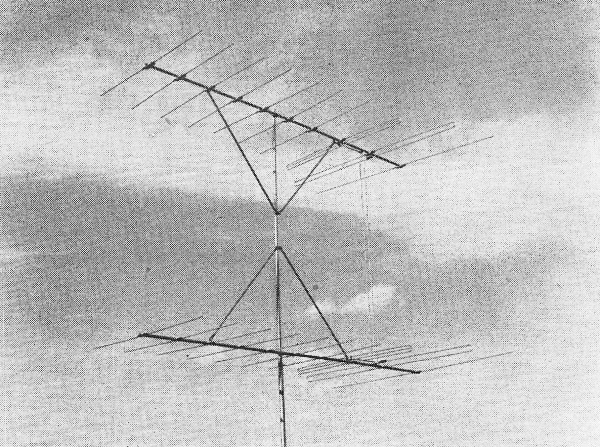
Futuramic Antenna

Futuramic Antenna has Yagi gain and directivity plus multi-channel
coverage.
By Harold Harris* and Harry Greenberg**
The recent end of the television freeze means that hundreds of new v.h.f. stations
will be going on the air in the near future. It also means that 30 of the present
stations will have to change channels. One of the many problems created by this
change and expansion is the need for new types of antennas.
In the past two years the Yagi has become one of the most popular fringe-area
antennas. Despite its high gain and excellent directivity it has one serious limitation.
The Yagi will work on only one or possibly two channels. Wherever existing channels
are changed or new v.h.f. stations are added, present Yagi antennas will have to
be augmented or replaced. All new installations will have to provide for future
channels.
What is needed is an antenna with the outstanding gain, directivity, and structural
qualities of the Yagi plus the ability to cover a number of channels. This article
explains the theory and operation of a commercial broad-band Yagi antenna, the Channel
Master Futuramic.
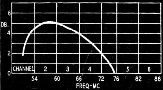
Fig. 1 - Folded dipole-reflector response.
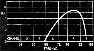
Fig. 2 - Folded dipole-director response.
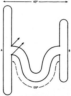
Fig. 4 - Basic Futuramic dipole spacing.
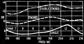
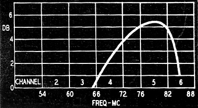
Fig. 6 - Response of high-band type.

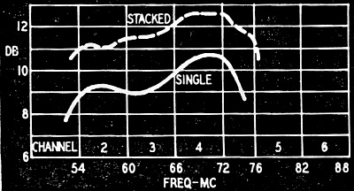
Fig. 7 - 0ne- and two-bay response curves for 3-channel
Futuramic.
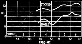
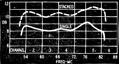
Fig. 8 - One- and two-bay response of another 3·channel
low-band Futuramic.

Fig. 9 - Response of Futuramic 4-channel low-band model
with 1 and 2 bays.
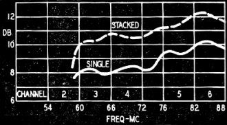
Fig. 10 - Another 4-channel Futuramic model.
Parasitic antennas
It will be helpful to review some of the characteristics of parasitic antenna
systems. The gain curve of a folded dipole with reflector cut for a specific channel
is shown in Fig. 1. Its response falls off sharply at the low end, but the
high-frequency end extends over two additional channels with gradually diminishing
response. A folded dipole with director (Fig. 2) has slightly higher gain than
the reflector type, but differs in two important respects: First, its bandwidth
is not as great; and second, its response drops sharply at the high end, and gradually
at the low end.
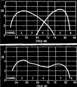
Fig. 3-a (top) - Matched dipole-reflector (low end) and
dipole-director (high end). Fig. 3-b (bottom) - Overall response of the combination.
Fig. 3 shows how these characteristics are used in the Futuramic antenna.
A folded dipole and reflector cut for channel 2 is combined with a folded dipole
and director cut for channel 5. The opposite slopes of the two antennas in the center
of the band (3-a) give uniform sensitivity over channels 2, 3, 4, and 5 (3-b). The
same principle enables two dipoles of proper length to cover the entire high band
(channels 7-13).
Adding directivity
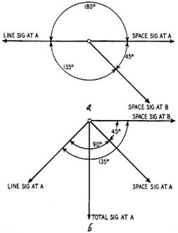
Fig. 5 - Phase relationships in spaced dipole system: (a)
signals coming from left; (b) signals arriving from right.
The next step was to make the combination unidirectional. Fig. 4 illustrates
the basic principle used in the Futuramic antenna. Dipoles A and B are cut respectively
for the low and high ends of the band to be covered. They are spaced 45 electrical
degrees (one-eighth wavelength) at the mid-band frequency, and are connected by
a section of transmission line 135 degrees (three-eighths wavelength) long.
The antenna feed points are at the terminals of dipole A.
A signal from the left hits dipole B through space 45 degrees after it hits dipole
A. This signal is then fed back from B through the line section, which shifts the
phase an additional 135 degrees. The feedback signal reaches dipole A 180 degrees
out of phase with the original signal. Thus signals from the left cancel at the
feed point. (Fig.5-a)
A signal from the right hits dipole B first. The space signal hits dipole A 45
degrees later, but the signal traveling through the line from B to A is shifted
135 degrees. As a result, two equal signals reach A 90 degrees (135 minus 45) apart,
and their sum is 1.4 times the original signal. (Fig 5-b.) The basic two-dipole
network thus has a 40% voltage gain (3 db) forward and rejects signals from the
rear.
In the commercial models, the transmission-line section is actually 60 degrees
(one-sixth wavelength) long, with the feed points 45 degrees from dipole B. This
compensates for the inductive signals, and for the capacitive reactance reactance
of dipole A on higher-channel of dipole B on lower-channel signals.
Increasing forward gain
Fig. 3-b shows that the natural sensitivity of the two-dipole system is
greatest at the low-frequency end of the band. A single reflector element (behind
the low-frequency dipole) raises the forward gain at the low end about 4 db. Additional
reflectors do not give any substantial increase in sensitivity. Seven director elements
provide high gain at the high end.
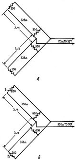
Fig. 11 - Yagi stacking methods: (a) Conventional stacking
with 300-ohm antennas and 325-ohm bars. (b) Channel Master Match system, using 200-ohm
antennas and 350-ohm bars.
A single Futuramic covers the entire high band (channels 7-13) and models were
designed for covering either three or four channels of the low band. Gain curves
for single and stacked antennas are shown in Figs. 6 through 10. In these figures,
the terms stacked and double-stacked refer to 2-bay and 4-bay antennas, respectively.
The high-band antenna can be stacked in four bays.
Note that antenna gain increases with frequency. This offsets the higher losses
in the lead-in, and tends to keep the voltage fed to the receiver constant for all
channels in the band.
The significant stacking gains were achieved by using the Channel Master Z-Match
system. Most television antennas are stacked with 3/8-inch tubing, spaced 3 inches
to give a characteristic impedance of 325 ohms. Since Yagi antennas are stacked
a half-wave apart, the stacking bars function as a pair of quarter-wave transformers,
transforming the impedance of each antenna to A different value at the feed points
in the center of the bar. The formula for the transformer is IMAGE HERE where ZM
is the impedance of the matching section (stacking bars), Z1 is the input
(antenna) impedance, and Z0 is the output (line) impedance.
When two 300-ohm Yagis are stacked with 325-ohm matching transformers, each Yagi
is transformed to 350 ohms at the feed points. The two 350-ohm impedances in parallel
equal 175 ohms, a mismatch of almost two to one (see Fig. 11-a). In the Z-Match
system, the center bar is taken out of the rear folded dipole, lowering the impedance
of the array to 200 ohms. Stacking bars (quarter-wave transformers) are spaced to
have 350 ohms impedance. The 200-ohm antennas are raised to 600 ohms each at the
feed points. The two 600-ohm impedances in parallel total 300 ohms to match the
transmission line (Fig. 11-b).
* Vice-president, Sales & Engineering, and
** Chief Development Engineer, Channel Master Corp., Ellenville, N. Y.
Posted December 22, 2021
|