|
June 1951 Radio-Electronics
 [Table of Contents] [Table of Contents]
Wax nostalgic about and learn from the history of early electronics.
See articles from Radio-Electronics,
published 1930-1988. All copyrights hereby acknowledged.
|
George Goubau (Library of Congress)
Who says engineers and scientists have no sense of humor? This is not an April
Fools joke or an attempt to punk you into reading the story. An Internet browser
with strict parental control settings enabled might even prevent this page from
even being displayed. In actuality, the term "G-String Transmission Line" was so
dubbed by its inventor, Dr. George Goubau, as a tribute to his own name - both
first and last. Out of an abundance of caution, I reference the Library of Congress'
"G-String" entry for the good
doctor and the device's legitimacy. A drawing similar to Fig. 1 in this 1951
issue of Radio-Electronics magazine can be seen on the chalkboard behind
Dr. Goubau in the LoC photo. To be honest, I do not recall ever having heard
of the G-string transmission line. Its enthusiastically, nearly evangelically extolled
virtues must not have panned out in real-world practice because we do not find G-strings
anywhere in modern microwave systems. Here is another photo of an actual G-string
system in the book "Images
of America: Fort Monmouth," which is where much of his research was done. Here
is yet another reference in a 1950 edition of the "CADO
Technical Data Digest." Finally, here is an honorable mention in a 1962 book
entitled, "Radio-Electronic
Transmission Fundamentals." Bonne lecture.
 Thanks to RF Cafe visitor Kevin A. for
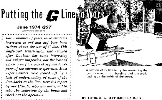
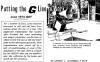
letting me know about this very extensive article by George Hatherell, K6LK, entitled,
"Putting the G-Line to Work"
which appeared in the June 1974 issue of QST magazine. Can it be a coincidence
that another guy whose name begins with "G" (George, even, like the originator)
writes an article about the G-String transmission line? Thanks to RF Cafe visitor Kevin A. for
letting me know about this very extensive article by George Hatherell, K6LK, entitled,
"Putting the G-Line to Work"
which appeared in the June 1974 issue of QST magazine. Can it be a coincidence
that another guy whose name begins with "G" (George, even, like the originator)
writes an article about the G-String transmission line?
 After seeing this article, RF Cafe visitor
and contributor, Bob D., reminded me of AT&T's
Project AirGig
5G system which appears to be a form of the G-String surface wave data communications
system. AirGig launches 24 GHz and 60 GHz waves along power lines and
then distributes signals locally to wireless access points in (Wi-fi routers, cellphones,
etc.). AC/DC power for the AirGig node is inductively obtained from the distribution
lines. Initial deployment is planned for 2021. The ARRL in 2016 posted a news item
entitled "AT&T's New 'AirGig'
Not Your Father's BPL," which alludes to Dr. Goubau's G-String technology.
Kevin A. referenced a 1974 QST article entitled "Putting the G-Line to Work."
AirGig is not likely to interfere with Amateur Radio activities because of its mm-wave
operation. Time will tell. After seeing this article, RF Cafe visitor
and contributor, Bob D., reminded me of AT&T's
Project AirGig
5G system which appears to be a form of the G-String surface wave data communications
system. AirGig launches 24 GHz and 60 GHz waves along power lines and
then distributes signals locally to wireless access points in (Wi-fi routers, cellphones,
etc.). AC/DC power for the AirGig node is inductively obtained from the distribution
lines. Initial deployment is planned for 2021. The ARRL in 2016 posted a news item
entitled "AT&T's New 'AirGig'
Not Your Father's BPL," which alludes to Dr. Goubau's G-String technology.
Kevin A. referenced a 1974 QST article entitled "Putting the G-Line to Work."
AirGig is not likely to interfere with Amateur Radio activities because of its mm-wave
operation. Time will tell.
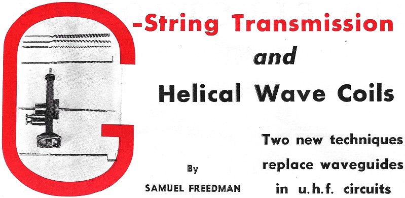
G-String Transmission Line and Helical Wave Coils
 By Samuel Freedman By Samuel Freedman
Two new techniques replace waveguides in u. h. f. circuits
Helical coils and simple straight wires can be used as a substitute for waveguides
to transmit electromagnetic waves at any frequency. For microwaves, the helical
coils can be unwound at their termination to serve as either non-directional or
directional radiators.
The waveguides which these two devices replace are in many cases made to special
dimensions and shapes and they are expensive. Waveguides are also narrow-band devices
and are rather critical with regard to frequency.
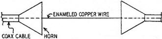
Fig. 1 - Sketch of the G-string transmission line. The horns
at each end keep the field pattern near the wire.
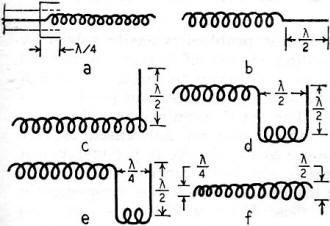
Fig. 2 - Circuits using the helical wave coil to get various
radiation patterns.
Helical wave, coils like those illustrated at the head of this article have been
used to replace both rigid and flexible waveguides. They first came into prominence
in the development of the broadband traveling wave tube amplifier. Depending on
their termination, they are capable of covering a wide range of frequencies.
More recently, the "G-string" has attracted wide attention because it is even
simpler and more economical than either waveguides or helical wave coils, and it
covers a wider frequency range with much less attenuation. The G-string makes possible
much longer microwave transmission lines having far less attenuation than is now
possible with current waveguide techniques.
The G-string, helical wave coil, and the waveguide each have their own advantages
and disadvantages, depending on how they are used, so that in many systems all three
are used. Neither the helical wave coil nor the G-string have been in use long enough
and in a sufficient variety of circuits so that it is possible to tell the full
extent of their usefulness. They will probably become most useful at those frequencies
where waveguides will be too small (super-high frequencies) or too large (ultra-high
or very-high frequencies) to be practical.
The G-string
A G-string (as used in electromagnetic transmission) is simply a long cylindrical
conducting wire as illustrated in Fig. 1. Its theory dates back to 1899 when
A. Sommerfeld described the possibilities of using such a line for wave propagation.
It was put to practical use not long ago by George Goubau and associates of the
Coles Signal Laboratory of the Signal Corps.
An enamel-coated copper wire serves admirably as a G-string (No. 12 or No. 8
will do). The dielectric layer of enamel reduces the radial extension of the electromagnetic
field so the waves tend to hug the wire in a large number of non-radiating modes.
Special launching horns are used to excite such waves in the arrangement shown in
Fig. 1. Starting from a coaxial cable, the outer conductor of the cable is
flared out as a horn and the central conductor becomes the G-string.

Fig. 3 - Cutaway sketch showing how a waveguide connects to a
helical coil.
The launching horn acts like a transformer which converts the field of the coaxial
cable or waveguide to the surface wave field and vice versa at the termination.
The larger the launching horn, the better will be the transition match. A new set
of horns is needed each time the direction of the run is changed. Adding a new horn
does not increase the energy at that point but it does confine the field to the
wire as it extends into its new direction.
The most obvious advantage of the G-string is that it is exceedingly simple.
While its full frequency range and attenuation characteristics are not yet fully
known, the author was told that, in the study of a 120-foot and also a 600-foot
length of G-string, the frequency range was from 200 to 30,000 megacycles and the
transmission loss was one-tenth that of a waveguide. The author also had a report
that it is possible to convey TV signals over such a line at the actual station
frequency. This may mean that the underground coax or the microwave relay stations
at vantage points on the horizon are no longer indispensable for network TV. The
landline may come back into its own because it is cheaper, more efficient, and is
independent of FCC frequency allocations.
The Helical Wave Coil
The helical wave coil is especially useful for microwaves because it can be used
as both a transmission line and a radiator. Energy flows along both the inner and
outer surfaces of the helical sheath. The field decreases to zero at the center
axis of the helix, so that it can be supported by a rod at its center if necessary.
The circumference of the helix must be small compared to the wavelength if it
is used as a transmission line. With the right termination, it will become a radiator.
If the circumference of the helix is increased to the order of one wavelength, it
becomes a radiator with maximum radiation in the direction of the helical axis,
and the field is nearly circularly polarized. This is called the axial or beam mode.
Other modes also can be excited. For example, a helix with dimension not quite large
enough for the axial mode will have a conical radiation pattern similar to those
in dielectric rods in which the electrical length of the radiator is either too
long or too short compared to its physical length. For certain diameters the radiation
pattern will be circularly polarized and normal to the helical axis. A linearly
radiated field can be obtained by terminating the helix in straight sections. End-fire,
broadside, and other multi-element arrays are easily made up by unwinding and winding
helical sections.
Circuit a of Fig. 2 shows a section of coax terminated by a helical wave
coil. The center conductor is wound into the helix and the outer conductor has an
additional quarter-wave collar. The circuit is tuned by adjusting this collar to
a critical length. If the end of the coil is dipped into aquadag or a graphite filler,
it converts the coil to an r.f. load termination.

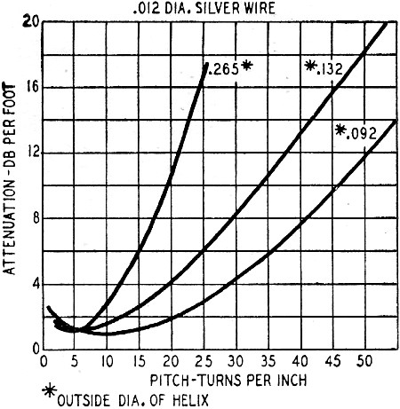
Fig. 4 - Attenuation characteristics of a helical wave coil versus
its pitch for a 3.2 cm wavelength (9.37 GHz).
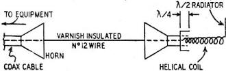
Fig. 5 - A G-string transmission line used with a helical wave
coil radiator.
The circuit of Fig. 2b may be fed in the same way as circuit 2a, but it
terminates with a half-wave straight horizontal section which is a radiator. Circuit
2c is also the same, but it has a vertically polarized antenna termination. Circuit
2d is the same as 2c with a second half-wave element to produce a figure-8 pattern.
A cardioid-type pattern is produced by 2e, which is the same as 2d except that the
section between the two half-wave radiators is reduced to a quarter wavelength.
The coil in 2f has a constantly increasing diameter which produces a circularly
polarized pattern.
The helix can be excited by a coaxial cable by gradually winding the center conductor
into a tapered helix, and at the same time terminating the outer conductor either
by a flared section (similar to that used by the G-string) or by a quarter-wave
coaxial choke. The latter is done by using a modified coaxial to waveguide transformer.
Fig. 3 shows a typical waveguide coupler.
When used as a transmission line, the helix should be wound to have a pitch of
4 to 10 turns per wavelength, and its diameter should not be greater than 0.2 wavelength.
How well the helix serves either as a transmission line or as a radiator depends
entirely on how it is made. This is controlled mostly by the diameter of the turns
in the helix, the spacing between turns, the length per turn, the total number of
turns, the angle of pitch forming the turns, and the diameter of the wire which
is used to wind the turns. These factors in turn determine the entire length of
the helix.
Fig. 4 shows three curves which give an idea of the characteristics of the
helical wave coil. They show how the attenuation losses increase as the pitch of
the helix increases. Each curve is for a helix with different outer diameter, and
they are calculated for a wavelength of 3.2 cm, which is a common wavelength
for many radars.
By increasing the helix diameter to more than 0.2 wavelength, the coil radiates
along or between its turns. Two such coils can be used as a coupling device to substitute
for the rotating joints required in radar antennas. By selecting the correct diameter
and pitch, the helical coil can be made to substitute for costly special waveguide
configurations. Flexible helixes can be used in place of flexible waveguides and
waveguide elbows.
The G-string can be used only as a transmission line. It is not so adaptable
as the helical coil, but it is much more efficient. Fig. 5 shows how the two
can be used in combination. In this case the G-string feeds the helical coil which
is used as both a transmission line and radiator.
Both the G-string and the helical coil are easy to construct and they are especially
useful where cut-and-try methods must be used to get the right circuit. Persons
not too familiar with microwave techniques can use them more easily because they
do not have the confusing frequency and cutoff characteristics of waveguides. The
energy fields are easy to detect because they are not fully enclosed between the
conducting surfaces. Further, the same setup can be used to cover a much larger
part of the microwave spectrum than can waveguides.
The author wishes to acknowledge the work of Glenn Walters of Palo Alto, California,
Professor John Kraus of Ohio State University, members of the Signal Corps, and
others engaged in research and development of helical wave coils and G-string lines.
Posted May 11, 2020
|