March 1958 Radio-Electronics
 [Table
of Contents] [Table
of Contents]
Wax nostalgic about and learn from the history of early electronics.
See articles from Radio-Electronics,
published 1930-1988. All copyrights hereby acknowledged.
|
Feedback has been widely misunderstood
by many electronics enthusiasts, even those who have a fairly extensive background
in circuit design (that which does not involve feedback). In fact, there have been
instances of articles being printed in magazines like Popular Electronics,
Radio-Electronics, etc., where the authors got relatively simple feedback
equations wrong due to improper summing of nodes, necessitating a correction in
a later issue based on reader feedback (a convenient and appropriate word for this
comment). This article discusses feedback in audio circuits to avoid distortion,
but the concepts apply to any frequency of operation. It is possible in many cases
to implement seat-of-the-pants feedback schemes successfully, but if you need a
specific response and guaranteed stability, nothing short of rigorous mathematical
applications will do the job.Getting Feedback Straight - What
it will and won't do in audio amplifiers

By Norman H. Crowhurst*
It's surprising how often feedback is expected to do something it can't possibly
do. For example, I recently met an enthusiast with an amplifier that put out about
48 watts comfortably and then ran into severe distortion. He was frantically trying
to use feedback to make the amplifier deliver what he wanted - a full 50 watts.
He couldn't understand why using enough feedback wouldn't push the output up just
this little bit!
Most material on feedback has been based on a theoretical treatment using the
algebra of feedback theory. This algebra cannot take into account everything at
once - if it did it would become so involved that no ordinary person could possibly
understand it. We use one piece of algebra to tell us the effect of feedback on
the gain of the amplifier, then we go over the algebra again and find out what its
effect will be on the amplifier's impedances, frequency response and distortion.
Each investigation uses a separate application of the same math. But this does not
prove that the amplifier will do all of these things in equal manner at the same
time. It depends on just what form distortion (and other things feedback is expected
to correct) may take.
Frequency response
Some presentations on feedback have suggested (with deceptive simplicity) that
as feedback tends to smooth out fluctuation in gain it must flatten the frequency
response - on the basis that deviation from flat in frequency response is merely
deviation in the gain of the amplifier at different frequencies. Some readers are
doubtlessly aware that his oversimplification of theory can often be the reverse
of what really happens. Due to phase shifts in the amplifier, frequency response
can often be accentuated by feedback, rather than flattened.
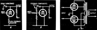
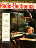
Fig. 1 - Three forms of single-stage feedback: a - current feedback in the
cathode; b - plate feedback to grid; c - Ultra-Linear, plates to screens.
Let's take feedback, step by step, starting from a single stage and using practical
examples to see how it can change the response in each case. Fig. 1 shows some
examples of single-stage feedback: simple cathode circuit current feedback, voltage
feedback from plate to grid on the same stage and the very useful Ultra-Linear circuit
where feedback from plate to screen is provided by taps on the output transformer.
With current feedback in a cathode circuit the feedback is effective right down
to DC at the low end. At the high end the only modifying factor is the stray capacitance
of the tube and its associated circuit. This eventually deteriorates the tube's
gain and hence also the feedback. So current feedback in the cathode does not modify
the low-frequency response at all, and the high-frequency response is modified according
to the distribution of tube capacitances.
In plate-to-grid feedback - shown in Fig. 1-b - a blocking capacitor between
the plate and grid keeps DC from feeding back to the grid and there is stray capacitance
to ground. The blocking capacitor introduces a rolloff at the low end in the feedback
circuit while stray capacitance to ground introduces a rolloff at the high end.
The low-end roll off causes feedback to fall off and stage gain to rise to its
no-feedback value if no other rolloff is introduced into the circuit to compensate
for this. The high-end rolloff is the same as that produced without feedback, but
feedback extends the frequency range by the same factor as it reduces gain. Thus,
if feedback reduces gain by 6 db, frequency range at the high end is extended by
a ratio of 2 to 1.
In the Ultra-Linear circuit (Fig. 1-c) the signal fed back from plate to
screen is coupled by the output transformer. At the low end of the frequency response
the transformer introduces a reactance shunting the plate circuit, due to its primary
inductance. When the tube is operating as a straight pentode, without coupling to
the screen, its source resistance is much higher than with Ultra-Linear feedback
introduced. This means that adding feedback extends the low-frequency response due
to the reduced source impedance the primary inductance shunts.
At the high end of the frequency response the transformer introduces a leakage
inductance between plate and screen so at some point the amount fed back to the
screen begins to fall off. This causes feedback to begin to fall off somewhere in
the higher frequencies. However, this does not show up in practice because there
is a larger leakage inductance between the whole primary and other windings on the
transformer than between the part of the primary feeding the plate and the part
coupled to the screen. So the other rolloffs in the amplifier circuit go into effect
before the reduction in feedback from plate to screen starts to make itself felt.
Two-Stage Feedback
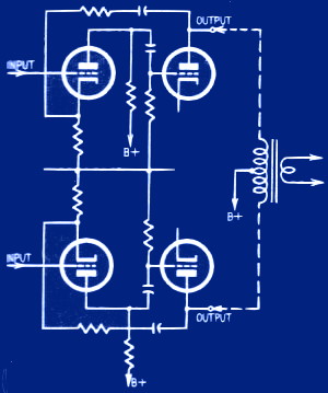
Fig. 2 - A form of feedback using two reactances in feedback
loop at each end of audio response. (Output transformer not part of feedback circuit.)
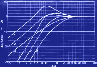
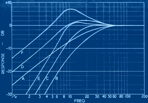
Fig. 3 - Sample low-end response curves for Fig. 2.
A - Original rolloff of each time constant; response of amplifier without feedback;
B - open loop response; C - round-the-loop response with 6-db feedback; D - amplifier
response with 6-db feedback (difference between curves A and B); E - round-the-loop
response with 12-db feedback; F - amplifier response with 12-db feedback (difference
between curves A and E).
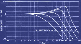
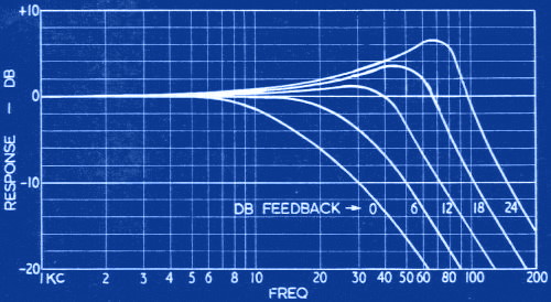
Fig. 4 - Sample high-end response curves for Fig. 2,
assuming loss due to stray capacitance gives identical roll-off with 3-db point
at 20 kc for each stage.
Now let's start on feedback over two stages. Take the circuit of Fig. 2,
which represents a driver and output stage with feedback from the output stage plates
to the driver cathodes. Considering the round-the-loop effect, here we have the
coupling capacitors from driver plates to output grids, and blocking capacitors
from the output plates to the driver cathodes, which contribute to low-frequency
response. At the high-frequency end we have stray capacitances which can be regarded
as shunting the driver and output plates, respectively.
Consider the low-frequency response. A first study might suggest that low-end
response could be made absolutely flat. By making the time constant of the interstage
coupling between driver and output equal to the time constant of the feedback arrangement,
the blocking capacitor in the feedback loop would cause a rise in frequency response
as feedback falls off, while the coupling capacitor between stages causes a similar
roll off in the forward response. The two having identical frequency characteristics
should result in a flat response. But this assumption ignores one fact.
What happens with phase when there are two or more coupling elements in the feedback
loop? If we use two identical time constants, as suggested, then more than 6 db
of loop feedback starts to show a peak in the loop response at the low end, due
to phase interaction. But 12 db of feedback shows a peak of about 1.25 db; 18-db
feedback shows a peak of about 3.6 db; 24-db feedback shows a peak of about 6.3
db, and every successive 6 db of feedback shows approximately 3 db more peak.
This effect is independent of how the coupling arrangements are distributed around
the loop. If one coupling element is in the feedback arrangement, the inverse of
the response due to feedback coupling must be added to this peaking effect. For
example, with 6-db feedback there is a slight peak of a little more than 2 db (curve
D, Fig. 3). With 12-db feedback the peak rises to about 7 db (curve F, Fig. 3)
and so on, due to the additional boost given by the coupling element in the feedback
part of the arrangement.
At the high-frequency end of the response there is no loss in the feedback part
of the arrangement. Losses due to both groups of stray capacitance from plate to
ground affect the forward response. The only place where loss would affect feedback
is at the cathode of the driver stage, where there is no loss worth mentioning.
Therefore, assuming the time constant of the stray capacitance from plate to ground
is the same for each circuit, the amount of peaking introduced by different amounts
of feedback in the loop response would apply without the boost effect due to part
of the loss being in the feedback path. See Fig. 4.
In this circuit (Fig. 2) the feedback does not include the output transformer,
so any frequency response contributed by the output transformer is added to the
response of the feedback measuring overall response.
Output feedback
The next question is: What happens when we apply feedback from the output transformer
secondary? So far we have discussed circuits where the factors contributing to rolloff
at the low and high ends are easily separable. But when we consider an output transformer
they are a little more tied up and perhaps not so easy to recognize.
In the output transformers of conventional push-pull amplifiers, considertion
of the low-frequency response, since it is caused by just the primary inductance
shunting the plate resistance of the output stage, is simple enough. Hence, for
low frequencies, performance is the same whether connected from primary or secondary
of the output stage. In fact, by connecting from the secondary, the blocking
capacitor can be eliminated and thus the possibility of achieving good low-frequency
response is somewhat improved.
At the high-frequency end the output transformer contributes two reactances.
There is the plate-to-ground capacitance, to which the output transformer contributes
primary-winding capacitance, and the leakage inductance between primary and secondary.
Since both of these contribute to high-frequency rolloff, by feeding from the secondary
of the output transformer back to the grid of the output stage, we have two reactances
contributing to high-frequency rolloff.
This means that peaking starts immediately there is more than a certain amount
of feedback, according to the relationship between the circuit constants. The circuit
shown in Fig. 5 never becomes unstable, no matter how much feedback we use,
but we do run into peaking similar to that produced by the two-stage circuit of
Fig. 2.
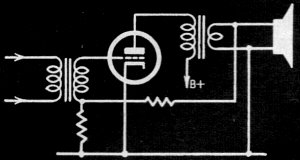
Fig. 5 - Feedback over single stage with output transformer.
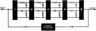
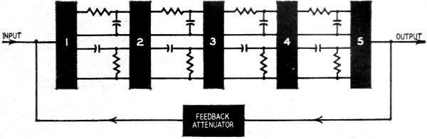
Fig. 6 - Basic factors in long-loop-feedback amplifier.
Numbered boxes indicate amplifier stages or phase inverters without frequency-discriminating
components.
If we attempt to feed back over more of the circuit than shown in Fig. 5.
from the output winding of the transformer, it becomes possible for feedback to
push the peaking up to the point where oscillation begins. This is where real care
is needed in the design.
The method of tackling this is to arrange the time constants contributing to
rolloff response at both ends of the frequency spectrum so they are as widely divergent
as possible. The best possibility of increasing the amount of feedback is to make
one of the time constants effect a roll off much closer to the passband of the amplifier
than all the other time constants.
For example, if four reactances contribute to an ultimate roll off, at each end
of the response, which is a common arrangement, then by having one time constant
at 100 times nearer the amplifier's passband than the remaining three, 24 db of
feedback can be used before peaking begins to show up at all. And almost 40 db of
feedback can be used before the amplifier becomes unstable. To achieve this range
with this particular configuration, illustrated in basic form by Fig. 6, the
roll off point at the low end for one of the networks could be 100 cycles while
the remaining three should be moved down to 1 cycle. Similarly, at the high end,
one rolloff could be effective at say 10 kc, while the remaining three should be
moved up to 1 mc.
To arrive at what the ultimate response will be, suppose we use 24-db feedback.
The first acting rolloff is extended by approximately the ratio represented by 24-db
feedback. This corresponds with a ratio of 16 to 1. So the 100-cycle rolloff is
pushed down to about 6 cycles, and the 10-kc roll off is pushed up to about 160
kc, both of which are well beyond the limits generally recognized as necessary in
an audio amplifier.
Readjusting our figures to finish up with an amplifier that is just about right
for audio, we could make the rolloff points for the low end 320 cycles with 3.2
cycles for the remaining three which leaves us with a 20-cycle rolloff for the low
end, and 1,250 cycles with the three additional rolloffs at 125 kc gives us an ultimate
rolloff at 20 kc.
Such a combination provides a satisfactory feedback amplifier for use on audio,
but the trend in most feedback-amplifier designs is to have a much larger margin,
and the figures first given are nearer to those used in actual design. Once these
figures are chosen, we have to stick with them to get successful performance.
This explains why it is necessary to insure that some stages respond out to 1
mc to get satisfactory performance out of the amplifier. A while ago someone asked
why Joseph Marshall added neutralizing to some of the stages in his Golden Ear amplifier
(Radio-Electronics, April, 1954). From this discussion we see that there can be
a good reason for doing this, although it might appear to be going to extreme limits,
until we realize the fundamentals necessary to achieve stability in a feedback amplifier.
So much for frequency response and stability problems. The statements made can
be substantiated by the necessary mathematics and, if any readers are doubtful about
them or want further detailed information for design purposes, they are referred
to my article, "A New Approach to Negative Feedback Design" (Audio Engineering,
May, 1953). But here we want to get on to the question of sorting out some of the
things that the mathematics seem to have left open.
Distortion
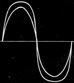
Fig. 7 - Amplifier output waveform at two levels, where
distortion sets in gradually.
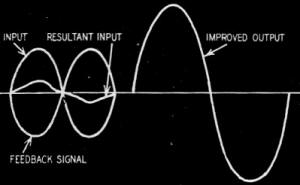
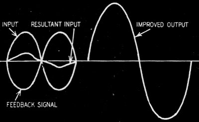
Fig. 8 - How feedback can improve the output in Fig. 7.
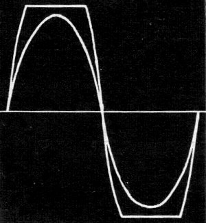
Fig. 9 - Amplifier waveform where distortion appears suddenly
as clipping. Feedback cannot help appreciably.
Let's revert to the question introduced at the beginning of the article. Can
feedback actually extend the output of an amplifier? We could go into a lot of theory
on this but probably the best way to illustrate the matter is to take some typical
waveforms from amplifiers we want to improve.
Fig. 7 shows the output waveform at two different levels for an amplifier
where the overloading effect is not too sudden - it runs into a gradual curvature.
This could be, for example, an amplifier employing power drive, so the output tubes
are driven into positive grid current, and there is power in the driver stage to
supply the necessary grid current. This type amplifier shows a rounding of the top
of the waveform before it begins to flatten. And this rounding can introduce considerable
distortion before actual clipping begins.
In this kind of amplifier, feedback can help. The feedback signal can make the
driver give a slightly more peaky waveform to offset the roundings, and the resultant
wave comes closer to the sinusoidal. This is shown in Fig. 8.
Now look at Fig. 9, which shows sample waveforms from an amplifier at two
different levels, where clipping occurs quite suddenly. This might be a push-pull
amplifier fed by a non-power-driver stage, so commencement of grid current at the
output tubes causes very abrupt clipping. Since the driver cannot supply any power
to the grids of the output tubes, nothing feedback can do will ever overcome the
clipping. If the driver delivers a small amount of power that starts to give a little
positive grid current in the output tube, rounding the corners of the clipped waves
slightly, feedback will be able to accelerate the rate at which this power is provided.
So applying feedback makes the output waveform even more squarely clipped than it
is without feedback.
In other words, feedback stands a chance of improving the waveform of an amplifier
below maximum output but, once clipping starts, feedback tends to make the clipping
sharper rather than to eliminate it.
Another effect of feedback on the overall distortion of an amplifier seems to
get overlooked. At lower levels feedback does reduce the total harmonic content
of an amplifier. But it also changes the harmonic present, and this change is not
always an improvement. This is best illustrated with some simple figures.
Suppose we have an amplifier that introduces a distortion of 5% third harmonic.
This could be due to too high a value for the plate load resistor for a pentode
in an early stage and the percentage might be almost independent of operating level
- 5% third harmonic would appear on signals of all levels. Now suppose this amplifier
has its gain increased, to make it possible to apply a total overall feedback of
40 db. This sounds quite good. We should be able to knock the 5% third harmonic
down to .05% third harmonic and probably we can.
But we have overlooked something which is illustrated in Fig. 10. To reduce
the third harmonic from 5% to .05% the input to the amplifier consists of a 100%
original input signal, offset against a 99% fed-back signal. To offset the 5% third
harmonic that the amplifier is going to introduce, the final input signal, made
up by the 100% minus the 99%, must contain a third-harmonic component almost 5%
in value but in opposite phase to the 5% the amplifier introduces. This 5% of third
harmonic goes through the amplifier as does the original 100% fundamental. Besides
offsetting the distortion produced by the fundamental, it produces some distortion
of its own, to the extent of 5% of 5%, at a harmonic which is the third of the third.
This produces 0.25% of ninth harmonic. So what our feedback has done is to reduce
the original 5% third harmonic to .05% and at the same time gives us a 0.25% ninth
harmonic we never had before.
Measuring this on a distortion analyzer, it will look as if the feedback has
produced an improvement, not quite as much as we calculated, but quite a good reduction
and so we are happy. But if we listen to the amplifier, it may not sound as much
better as we expected, because 0.25% ninth harmonic can be quite noticeable.
More than this, we have only considered the effects of feedback on a single sine
wave. When we come to consider intermodulation products, we find them multiplying
up out of all proportion, and a great variety of intermodulation products is introduced
by an amplifier designed in this manner. The resulting reproduction sounds extremely
muddy, although the figures might appear quite presentable - an overall distortion
figure of 0.25% is not generally considered to be too bad.
You Can't Eat Your Cake ...
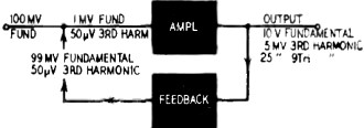
Fig. 10 - How feedback affects harmonic distortion.
Before leaving the question of distortion let's look at one more aspect. When
we apply feedback, sometimes we achieve more than one purpose. We can make feedback
do two or three things at the same time, but sometimes we use up the feedback on
one purpose so that it is not available for others. This can happen, for example,
where feedback is used to change an impedance.
Suppose we use a regular type of feedback amplifier to provide a lower source
impedance than its non-feedback cousin. Next we apply an output load equal to the
source impedance.
We calculate the amplifier performance on the basis of either no load impedance
or the optimum load impedance for the output tubes used. So it is not really legitimate
to change just the load impedance and expect the same performance from the feedback
amplifier. To find out what really happens we should recalculate the performance
of the amplifier on the basis of the revised load impedance. What we will probably
find is that the new load impedance allows much smaller output before distortion
starts to be really serious and that feedback has become almost nonexistent, due
to the change in loading impedance reducing the gain of the output stage.
Just take some figures to illustrate. Suppose that the optimum load of a certain
output stage is 8,000 ohms and its source resistance is 3,000 ohms. By applying
26 db of feedback, the source resistance can be reduced from 3,000 ohms to 150 ohms.
Now suppose we load the amplifier with a 150-ohm load (by the same matching transformer
used for the 8,000-ohm load).
Let's take the feedback off for a moment and see what happens by changing the
load in this condition. When we take the 8,000-ohm load off, the gain rises, due
to an open-circuit condition, in the ratio of 11/8. Then, when the 150-ohm load
is connected in place of it, gain is reduced in the ratio of 150/8,150. The net
result, is reduced gain due to the change of load, by a factor of 1/40.
With the 8,000-ohm load the feedback was designed to be 26 db, which is a ratio
of 20/1. As the gain has already been knocked down by a ratio of 40/1, the feedback
factor will not be only 0.5, instead of 20. The amount of feedback resulting from
0.5 fed-back signal injected in series with the input is only 3.5 db.
This can do little toward reducing distortion. To be precise, it will reduce
distortion by a factor of 2/3. If connecting a 150-ohm load to the output of this
stage produces a distortion of 20%, which is quite a normal figure for such low
loading, feedback reduces this only to 13.33%, which is still a very high distortion
figure.
However, the amplifier will have an apparent source impedance of 150 ohms, which
is what we have used the feedback up for. All of which reminds us of the old proverb
about eating one's cake and having it too.
Hum and Noise Reduction
Another thing feedback is used for is to reduce amplifier hum and noise. In other
words, to clean up any unwanted sounds not present in the input.
Many users have applied feedback with this object in view, only to be disappointed
in finding either that it has had no effect whatever or that it has had the reverse
effect. Let's just see how this can be.
First, let's take hum. One point not to be overlooked is: when adding feedback
to an amplifier that must give full output for a specified input, more gain is necessary,
so adding feedback leaves us with the same gain we had originally. Generally speaking,
hum gets induced in the earlier stages of an amplifier so, if we're going to apply
20-db feedback, we need 20 db more gain in the first place, and the hum will get
20 db more amplification before feedback is applied. Application of feedback then
knocks the hum back to where it started from.
This is assuming that the hum is injected somewhere within the feedback loop.
If however, as sometimes happens, the hum creeps in outside of the feedback loop,
it is possible for the addition of feedback actually to increase hum instead of
reducing it.
Noise in feedback amplifiers actually tends to be higher, other things being
equal, than in non-feedback amplifiers, The reason for this is fairly easy to see.
Suppose noise at the input 0 a non-feedback amplifier is equivalent to 10 μv
at the grid of the first stage, which is intended to accept an input level of 10
mv. If 20 db of feedback is added to the amplifier, it will need 20 db more gain,
and hence should be able to load with only 1 mv on the first stage grid. But this
grid will still have a noise level of 10 μv. If the feedback is successful in
reducing the noise level by the complete amount of feedback added, then this reduces
the effective noise back to its original 60-db discrimination. But this depends
on every element in the noise signal being fed back completely out of phase with
the original noise signal.
The lower component frequencies in noise may be successfully reduced by the 20
db in this way but, at the upper end of the response, where the random happenings
that constitute noise are of shorter duration, feedback cannot keep pace with the
changes and hence fails to make a reduction of the full 20 db.
Therefore, the noise level is higher in the feedback amplifier and it tends to
concentrate in the upper frequencies.
Also - if due care has not been paid to eliminating the peaking effect mentioned
earlier-the noise will definitely be colored by peaks at both ends of the frequency
response, resulting in the familiar hissy, boomy background common with amplifiers
using a large amount of feedback. This is quite independent of the fact that frequency
response throughout the audio range may be quite flat.
Does Multi-Loop Help?
A final question concerns the relation between single-loop and multi-loop feedback,
in all these points of discussion. In an earlier article, I called attention to
some of the deficiencies of feeding back over the whole amplifier ("Why Feed Back
So Far?," Radio-Electronics, September, 1953).
The use of multi-loop feedback does overcome some of these deficiencies. The
short-loop feedback, toward the output end of an amplifier, stabilizes that part
of the amplifier and usually extends frequency response beyond the audio range to
give a satisfactory margin for application of longer-loop feedback. Also the short-loop
feedback, over a section of the amplifier operating at higher level, will not aggravate
hum or noise troubles in the same way as the equivalent amount of feedback applied
in an overall loop would.
It is advantageous to apply as much feedback as possible over a shorter loop
and minimize the long-loop feedback, if possible, avoiding any feedback right back
to the input stage at all. It is better to take the feedback to a stage immediately
following the input stage, so the first stage operates at maximum gain and gets
the signal level above the inherent noise of tubes and other things, before we introduce
any feedback.
This last remark applies especially to high-gain amplifiers or preamps which
operate from low level inputs. Amplifiers designed to operate from high-level inputs
are quite satisfactory with overall feedback, provided precautions are taken to
minimize the possibility of conditional stability.
* Author of Understanding Hi-Fi Circuits (Gernsback Library).
Posted December 2, 2019
(updated from original post on 1/24/2014)
|