|
June 1971 Radio-Electronics
 [Table of Contents] [Table of Contents]
Wax nostalgic about and learn from the history of early electronics.
See articles from Radio-Electronics,
published 1930-1988. All copyrights hereby acknowledged.
|
Parenthetically mentioned
in this introductory article on lasers is a "Mie" type particle. At first I thought
maybe it was a typo, but in fact it refers to
Mie scattering, which is the dispersion of electromagnetic waves
by isolated spheres, stratified spheres, infinite cylinders, or other geometries where
radial and angular dependence are independent. Two simple experiments are described
for demonstrating light scattering and absorption similar to what occurs in the
atmosphere. Whereas procuring the 2.5 mW laser source and to a lesser extent
suitable light meter would have been difficult and expensive in 1971 when this was
published in Radio-Electronics magazine, today's cheap equipment puts them
within the budgets of almost anyone. Many of the <$10
cat toy lasers provide plenty of power. In fact,
you have most likely already witnessed the light absorption phenomenon when using
such a laser by noticing the scattering of dust particles in the air. To a large
degree, the fascination with lasers has ebbed in the last half century since
they have gone from science fiction wonders to having a ubiquitous presence in
our lives.
RF Cafe visitor Zachary Fox sent me
a note regarding this article. Mr. Fox is an avid laser experimenter /
hobbyist who has a blog on the
Laser
Pointer Forum website where he documents his activities. He recently
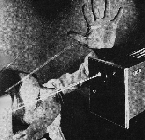
purchased a document containing the actual photograph shown in the article
that shows RCA Solid State Research Laboratory scientist Dr. Karl G.
Hernqvist projecting the 24 spectral lines of a helium-selenium laser onto
his hand. What was a big deal in 1971 is ho-hum technology today, just like what
is ground-breaking today will be ho-hum in 50 years. We should be grateful for
people like Zachary who collect and preserve these parts of history so that
someone with no interest doesn't throw it out with the trash.
Basic Laser Experiments

Photo courtesy RCA Princeton Labs
By U.S. Bureau of Radiological Health
The following experiments demonstrate properties of light and other electromagnetic
radiation using the laser. The experimenter is expected to be familiar with the
classical elementary theory of light; therefore, explanations are kept to a minimum.
The experiments produce effective demonstrations with minimum equipment and maximum
safety.
Light detection and intensity measurements can be made with a photographic light
meter, preferably one that uses a CdS (cadmium sulfide) detector. The light levels
from a 2.5-mW laser will not overdrive the meter and used meters can be purchased
in camera stores. The meter's response to light is not linear, however, and response
must be calibrated against a more accurate standard.
Experiment 1 - Scattering of Light
Explanation:
When light passes through the atmosphere, it is scattered by the large number
of gas molecules and particles that make up the atmosphere. Objects are visible
only because of the light they scatter toward the viewers' eyes. For this reason
(i.e., the lack of light scattered toward them) astronauts are largely in the dark
when they travel in orbit beyond the earth's atmosphere. For this same reason, an
observer may not see a laser beam headed across his path. On the other hand, if
smoke is blown into the path of a laser beam, it immediately becomes visible.
Equipment Necessary for These Demonstrations:
1. Laser
2. Display tank
3. Support for display tank
4. Milk
5. Aerosol room deodorizer or smoke source
6. Liquid detergent
7. Ink
8. Boiled or distilled water
9. Detector (CdS light meter with red filter)* see note below
10. Mirror
11. Pivot mount for mirror
12. Protractor
13. Ruler
14. Thick slab of glass
15. Prism (45° -45° -90°)
16. Polarizing filters (3)
17. Small test tubes
18. Quarter wave plates (2) doubly refracting, red
19. AgNO3
20. Single-slit diffraction aperture
21. Double-slit diffraction aperture
22. Circular diffraction aperture
23. Divergent lens
24. Hologram
25. White paper
26. Transmission grating
27. Razor blades
This mechanism of optical scattering varies with the size of the scattering particles.
Particles such as smoke may be considered "large" if their radii approach the wavelength
of the incident light. The scattering from such particles is referred to as large-particle
(i.e., Mie) scattering. In this type of scattering the particles may be considered
as opaque spheres which scatter according to the principles of the diffraction theory.
It is this type of scattering that can pose a potential hazard when high-powered
lasers are used in the atmosphere.
Particles whose radii are much smaller than the wavelength of the incident light
(radius < 0.05λ), scatter by a different mechanism called Rayleigh scattering.
In this type of scattering, each microscopic particle acts as an electric dipole,
reradiating the incident wave by electrically coupling into resonance with the electric
field of the incident light. This type of scattering can be seen by observing different
regions of the daylight sky through a polarizing filter.
Materials:
Laser
Display tank
Boiled or distilled water
Milk
Smoke source or aerosol can
Experimental procedure:
Large particle or diffraction scattering
Direct the laser beam so it passes through the clean display tank filled with
boiled or distilled water. The path of the beam will probably not be visible in
the water. Add a small amount of homogenized milk to make the water turbid. The
path will then become visible. Instead of milk, a concentrated solution of colloidal
silica solution can be added to the water to make a permanent display solution.
Large particle scattering can also be demonstrated by blowing smoke or the spray
from an aerosol can into the path of the laser beam.
Experiment 2 - Absorption of Light
Explanation:
In passing through a material, laser light, like all electromagnetic radiation,
undergoes absorption which can be expressed by the exponential relationship I =
Ioe-μx, where μ is a function of the absorbing material
and the wavelength of the light, and x is the thickness of the absorbing material.
If a green piece of cellophane is placed in the path of a helium-neon laser beam
(i.e. red light), there is a substantial reduction in the beam intensity. If, on
the other hand, a red piece of cellopane is used with the same beam, relatively
little absorption occurs. This principle of selective absorption of light from laser
beams with given wavelengths is used in some of the commercially available protective
goggles sold for use with lasers. This experiment demonstrates both quantitatively
and qualitatively how the absorption of light depends upon the thickness of the
absorber.
Materials:
Laser
Display tank
Liquid detergent
Detector for measuring light intensity
Ink
Experimental Procedure:
Prepare a display solution by adding a few drops of a liquid detergent to water
and stir until it is uniformly mixed. Fill the display tank with this solution and
project the laser beam into the tank so that the path of the beam is clearly visible.
Now add a drop or two of blue or black ink to the solution and stir until the solution
is uniform. Notice how this causes beam intensity to decrease rapidly as it penetrates
further into the solution. Continue to stir in ink a drop at a time until the beam
vanishes (i.e. is completely absorbed) before it reaches the opposite end of the
tank.
To make a quantitative measurement of the exponential absorption of light in
a material, direct the laser beam onto a detector which measures light intensity
or beam power. Record this value. Using various pieces of absorbing materials such
as a semi-opaque plastic, insert one thickness at a time, gradually increasing the
thickness of the material through which the laser beam passes. Record the light
intensity for each value of the total thickness of the material and plot the data
on semi-log paper. What is the shape of the line obtained? Why?
Posted April 17, 2019
|