Wax nostalgic about and learn from the history of early electronics.
See articles from Radio-Electronics,
published 1930-1988. All copyrights hereby acknowledged.
Magnet on a TV screen.
When I saw the images in this "Electron Shadows Map Force Fields" article from
a 1949 issue of Radio-Electronics magazine, the first thing I though of
was how as kids back in the 1960s we would hold magnets against the front of the
television cathode ray tube (CRT) to see how they distorted the picture. If I still
had a CRT TV or computer monitor around, I'd take some photos of it for the sake
of those who have never seen what happens. The difference between that and the images
formed here is that the professionals inserted the object of interest directly in
the electron beam, between the cathode and the fluorescent glass grid. As with the
images in the article, magnets of various shapes created unique responses. If you
drag the magnet across the face of the CRT, the pattern would follow it and, depending
on the strength of the magnet, would leave a fluorescent persistence trail behind
it. The danger, of course, was that in doing this you were causing a much greater
intensity of electrons hitting the fluorescent dots on the mask so they glowed much
more intensely than designed for. My parents had a conniption fit when I pulled that
trick on our new color television and the afterglow remained for many minutes. It's
a darn good thing the rare earth supermagnets we have now were not available back
then, or I would definitely have ruined the tube.
Fig. 2 - Magnetized wire in path of beam distorts grid lines.
New technique makes magnetic and electrostatic fields visible to the eye.
Next time you see a light shining against a wall and decide to improve the opportunity
by making hand shadows resembling ducks and rabbits, you may feel a little kinship
to serious-minded scientists of the National Bureau of Standards. These men are
using shadow pictures too, though for a purpose far removed from innocent enjoyment.
Their shadow-casting rays are not light, but electron streams projected on a fluorescent
screen or photographic plate. And the shadows, cast by electric and magnetic fields
in a technique developed by the Bureau's Dr. L. L. Marton, are yielding important
information on hitherto invisible phenomena.
Figs. 1 and 2 show how one typical experiment was conducted. In Fig. 1 a stream
of electrons emitted at the left is focused by a magnetic lens, much as a glass
lens would focus light. The beam then converges at the focal point: the electrons
deflected downward by the lens continue to travel downward and those deflected upward
continue upward. The focus at this "crossover" point is very sharp. Thus the crossover
is a virtual electron source.
Between the crossover and the photographic plate or fluorescent screen is a mesh
of fine wires, so that the plate shows an enlarged gridiron pattern.
The field to be analyzed is placed between the point electron source and the
magnetic lens. Fig. 2 illustrates what happens when a piece of recording wire which
has been magnetized by a series of evenly spaced short pulses is examined. The magnetic
field around the wire distorts the rays from the source before they reach the lens,
the amount of distortion at any point depending on the intensity of the magnetic
field at that point.
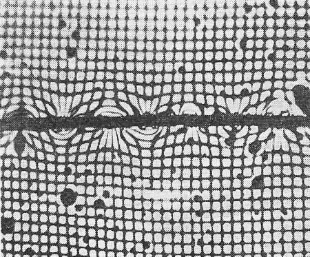
Fig. 3 - Pattern of the magnetized wire.
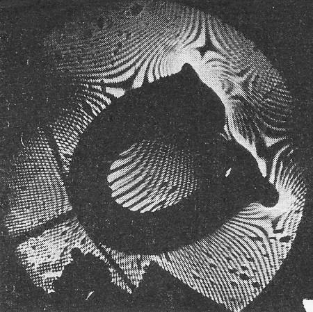
Fig. 4 - Pattern of a horseshoe magnet.
Because electron rays have been displaced, the focus at the crossover is disturbed.
It becomes larger, and the virtual source of electrons which it forms is no longer
simple. When the diverging beam reaches the wire mesh and casts its shadow on the
screen, the even pattern of the mesh no longer appears. The disturbed rays of the
source make curves and aberrations in the gridiron, vary the sharpness of focus,
and make strange-looking whorls.
An enlarged photograph of the screen of Fig. 2 is shown in Fig. 3. Another picture,
the pattern distorted this time by an ordinary horseshoe magnet (you can see the
magnet's shadow), is Fig. 4. With the aid of complex mathematical formulas, researchers
can measure and evaluate the distortion of the mesh pattern and determine exactly
the strength and nature of the magnetic field set up. Even without a scientific
background, however, it is easy to see the bulges above and below the shadow of
the wire in Fig. 3, indicating the alternating magnetic field induced by the recorded
pulses.
The electronic "shadowgraph" is expected to allow exploration of complex electric
and magnetic fields of very small size, its special value being that field strength
at any point can be measured. Many of these fields could never before be evaluated
because a probe any larger than an electron disturbs the field. Investigation of
the fundamental nature of ferromagnetism, for instance, is now under way at the
Bureau of Standards. Space - charge fields, fields produced by contact potentials,
charge distribution in gaseous plasma, waveguide problems - all these and more will
yield their secrets to the probing electron ray.
One of the important fields the technique may be applied to is waveguides. Often
the shapes of waveguides are too complex to allow mathematical analysis and the
engineer depends on experiment. By measuring the fields in waveguides of various
sizes and shapes with electron shadows, it may be possible to set up formulas to
predict performance accurately and eliminate much guess work.
RF Cafe began life in 1996 as "RF Tools" in an AOL screen name web space totaling
2 MB. Its primary purpose was to provide me with ready access to commonly needed
formulas and reference material while performing my work as an RF system and circuit
design engineer. The World Wide Web (Internet) was largely an unknown entity at
the time and bandwidth was a scarce commodity. Dial-up modems blazed along at 14.4 kbps
while tying up your telephone line, and a nice lady's voice announced "You've Got
Mail" when a new message arrived...
Copyright 1996 - 2026
All trademarks, copyrights, patents, and other rights of ownership to images
and text used on the RF Cafe website are hereby acknowledged.
All trademarks, copyrights, patents, and other rights of ownership to images
and text used on the RF Cafe website are hereby acknowledged.