|
December 1964 Radio-Electronics
 [Table of Contents] [Table of Contents]
Wax nostalgic about and learn from the history of early electronics.
See articles from Radio-Electronics,
published 1930-1988. All copyrights hereby acknowledged.
|
Prior to the advent of
meters with a super high input impedance (>1 MΩ) featuring field
effect transistors (FETs), accurate use of a voltmeter or ohmmeter required
knowledge of the meter's internal resistance and the resistance of the device
under test (DUT). As can be seen in Figure 2, various range settings on the
meter resulted in different internal resistances. The internal resistance of the
meter in series with the resistance of the DUT form a voltage divider where the
indicated voltage is less than that which would be indicated if the meter's
internal resistance was much higher. Author Robert Middleton presents examples
of possible errors when measuring voltage, current, and resistance. Many modern
digital multimeters (DMMs) have an input impedance of at least 10 MΩ, so very
few scenarios would require minding the meter characteristics. With modern DMMs
there is also no need to learn how to interpret the multiple needle scale
markings, or to take care to avoid parallax error as a result of not looking at
the needle from directly perpendicular to the scale markings, or keeping track
of the reading units (mV, V, mA, A, Ω, kΩ, MΩ, etc.) Life as a meter reader is
certainly much simpler these days.
More Meters for Beginners
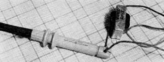
Fig. 9 - Hewlett-Packard current probe clamped around insulated
transformer lead.
By Robert C. Middleton
Most of the meters used in TV servicing have test leads. The resistance of the
test leads is important on the R x 1 range of an ohmmeter. Fig. 1 shows the basic
principle of ohmmeter action. An internal battery supplies current to a multiplier
resistance R. This current flows through the meter movement, through the test leads,
and through Ro, resistance to be measured. This diagram, which is reduced
to the essentials, makes it obvious that the test leads will introduce an error
in measurement if their resistance is abnormally high. Thus, if the leads become
frayed internally, for example, Ro will appear to have a falsely high
value.
This error might seem unimportant in a practical ohmmeter which includes a zero-adjust
control (Fig. 2). The zero-adjust control is useful in setting the pointer to reference
zero on the scale, when the battery voltage falls off from its "fresh" value. Hence,
you might conclude that the zero-adjust control compensates for test lead resistance.
To illustrate the error of, such a conclusion, let us take a practical example.
A peaking coil has a resistance of 5.5 ohms. The ohmmeter reads correctly when
the test leads are in good condition. A frayed lead caused the ohmmeter to indicate
that the coil's resistance was 4.6 ohms even though the ohmmeter was correctly zero-set.
The abnormal lead resistance subtracts from the true resistance value.
Battery Condition
Fig. 2 will show that the same basic error crops up when the ohmmeter battery
approaches the end of its useful life.
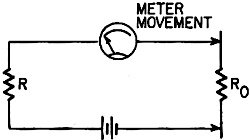
Fig. 1 - Basic Ohmmeter circuit.
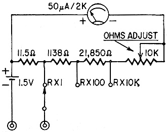
Fig. 2 - Complete practical ohmmeter circuit.
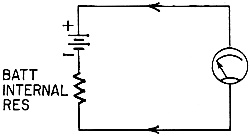
Fig. 3 - Batteries have internal resistance.
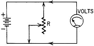
Fig. 4 - Measuring a battery's internal resistance.
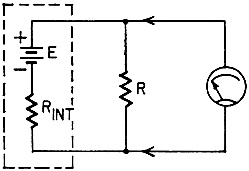
Fig. 5 - When the internal and load resistances are equal, voltmeter
indicates exactly half of battery's unloaded terminal voltage.
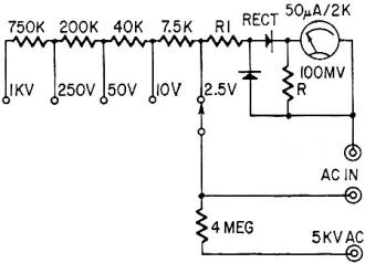
Fig. 6 - Above, an ac voltmeter circuit. Used with special scale
calibrated in db (below), meter becomes db indicator.
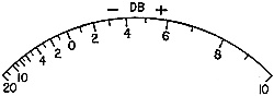
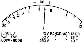
Fig. 7 - Pointer shows 5 db on lowest range (2.5 volts full scale).
On 10-volt range, add 12 db (according to data in instruction book or on meter scale).
Hence pointer, still at 5-db mark, reads 17 db.
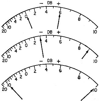
Fig. 8 - On top, a 6-db interval. Center, another 6-db interval.
Bottom, a 20-db interval.
Ohmmeters, dB Scales, Current Probes
Fig. 3 shows the reason. A battery has internal resistance. When the battery
is fresh, its internal resistance is low. When the battery weakens, its internal
resistance increases although its emf (electromotive force) remains practically
the same. In other words, a weak battery will seem to be good if tested with an
ordinary voltmeter, Under load, its voltage measures below normal.
Such a battery appears "good" on a voltmeter test, and "weak" under load because
a substantial portion of its emf is dropped across the abnormally high internal
resistance. In an ohmmeter, the battery's internal resistance is added to the test-lead
resistance. Hence, a weak battery has the same effect as defective test leads. It
is easy to measure the internal resistance of a battery (Fig. 4).
First, measure the battery voltage on open circuit. Then connect a rheostat (R)
across the the battery as in Fig. 4, and set the rheostat to the point where the
voltmeter indicates one-half of the open-circuit voltage. The resistance of the
rheostat is then equal to the battery's internal resistance. For example, a typical
"good" size-D flashlight cell might have 0.4 ohm internal resistance.
This test works as shown in Fig. 5. When load resistor R has a value equal to
the internal resistance Rint, a voltage divider is set up which applies
one-half of the battery's emf to the voltmeter. Note that this is also the basic
principle used in ordinary battery testers, which indicate good or bad on the basis
of a battery's terminal voltage under normal load.
Testing the Test Leads
If you suspect that the test leads are frayed internally or that contact resistance
is high, it is easy to check. Remove the leads from the ohmmeter and replace them
with a short jumper of heavy copper wire. Turn the zero-adjust control to bring
the pointer to zero. Then remove the jumper and plug in the test leads. Short the
leads together and note the meter reading. A typical value is 0.1 ohm. A substantially
higher value, such as 1 ohm or more, confirms your suspicion.
The Decibel Scales
These are used chiefly in audio test work. Unlike the voltage scales, a decibel
scale (Fig. 6) is nonlinear. Its usefulness is based on the fact that the perception
of loudness is proportional to logarithmic units like decibels, and not to voltage.
Ten decibels equal 1 bel. When the system was established, it was based on the premise
that 2 bels represented a sound level twice as loud as 1 bel. As a matter of fact,
many persons will judge that an increase from 1 bel to 1.8 bel, for example, doubles
the loudness of a sound. This difference in individual judgments, however, does
not affect the utility of db measurements now that the db has been established and
its meaning fixed.
As illustrated in Fig. 7, the decibel ranges are referred to a standard load
such as 600 ohms. In other words, unless the test leads are applied across a 600-ohm
load, the db indication will be incorrect. What is the reason? Simply that the decibel
is fundamentally a power ratio, and a vom is not a power meter. Since a vom operates
as a voltmeter on its db ranges, it must be applied across a known resistance so
that the scale reading will be proportional to power.
This is not to say that db measurements are meaningless when made across other
than the standard load value. For example, if both the input and the output of an
amplifier have the same impedance it is possible to make db input and output measurements
and to subtract the input reading. The difference is the actual gain of the amplifier
in db. But note carefully - both the individual measurements are incorrect (in absolute
terms), although the difference between the readings is a valid, correct value.
It is not possible to use this method of measuring gain when amplifier has different
input and output impedances. In such a case, rather involved correction factors
must be used. They are often impractical in a busy shop.
It is essential to add the specified number of db to the scale reading when you
use any range other than the first ac-voltage range, as in Fig. 7. To put it another
way, if the vom is switched to its 2.5-volt range, the db scale reads directly.
But if the instrument is switched to its 10-volt range, we must add 12 db to the
scale reading. Note the positive and negative scale sectors above and below zero
db. These won't cause confusion, if you remember simply to observe the interval
between readings (Fig. 8). In other words, if the first reading is -10 db and the
second reading is +10 db, the total interval is 20 db.
Current Probes
Until recently, current (ac) had to be measured in one of two ways. Voltage can
be measured across a series resistor in the circuit, and the current calculated
from Ohm's law. If there is no series resistor, the circuit must be broken. This
of course is time-consuming, and limits the convenience of current tests. In most
shops, current is measured only when absolutely necessary.
However, it is now possible to measure current as easily and quickly as voltage.
In fact, it is easier to measure current with a current probe (Fig. 9) than to measure
voltage, because no connection is made to the circuit. The current probe (made by
Hewlett-Packard) is basically a miniature "half-transformer" enclosed in a probe
housing. Clamped around a wire, the probe becomes the secondary, and the wire is
equivalent to a one-turn primary. Circuit loading is extremely light, because there
is only a small magnetic coupling to the wire. The current probe is shielded, so
it does not respond to electrostatic fields. Only the magnetic flux surrounding
the wire contributes to the probe output.
The probe is used with a vtvm. It contains a transistor amplifier and a gain
control (only a maintenance adjustment). Thus, the probe can be calibrated to read
current values with high accuracy. Such probes are available with uniform response
from near de to 400 cycles. The probe illustrated in Fig. 9 is designed for ac measurements
only, and has flat response from 60 cycles to 15 mc.
It is not practical to use a current probe with a vom, because the input resistance
of the instrument changes when the range switch is turned. The probe would have
to be recalibrated each time the vom range was changed. On the other hand, a vtvm
has constant input resistance on all ranges.
The probe indicates current on the voltage scales of the vtvm. A typical probe
calibration factor is 1 millivolt per milliampere. Thus, a current flow of 75 ma
produces a probe output of 75 mv. If small currents are to be measured, this type
of probe is used with an audio vtvm, which has suitable low-voltage ranges.
Posted February 26, 2024
|