|
February 1951 Radio-Electronics
 [Table of Contents] [Table of Contents]
Wax nostalgic about and learn from the history of early electronics.
See articles from Radio-Electronics,
published 1930-1988. All copyrights hereby acknowledged.
|
If you are familiar
with aircraft electronic navigation systems, reading in this 1951
Radio-Electronics article's opening paragraph about how "Omnirange aircraft
navigation will make air travel safe, dependable, and predictable regardless of
visibility, and volume of air traffic," really makes you realize how far we have
come in the last seven decades. The network
VOR (VHF Omnidirectional Range) station revolutionized aviation by enabling
precision navigation using relatively simple, reliable, and inexpensive
equipment in the cockpit which enables pilots to fly from waypoint to waypoint
across the country. Eventually, five variations of VOR evolved with ranges going
from 25 nautical miles (~29 statute miles) up to 130 nm. The addition of TACAN
(TActiCal Air Navigation) provided slant distance information to or from the
VORTAC station. Since the introduction of full precision
GPS
(Global Positioning System), when the U.S. government unclassified the "P-code"
which intentionally denied commoners access to the high precision mode, GPS has
been replacing VOR/VORTAC as the dominant means of air navigation for both VFR(
Visual Flight Rules) and IFR (Instrument Flight Rules) operation. My couple
years of general aviation in the late 1970s involved a VOR and Direction Finding
receiver in a Piper Colt airplane. Dead reckoning with a good pair of eyes was
considered the primary mode of navigation for VFR trainees like me, with the
other systems being luxuries for secondary use or in emergency situations (like
when stupidly flying into a cloud). While recently flying as a passenger in a
friend's Cessna 172, the only navigation he used was GPS being displayed on an
iPad clipped to the control yoke. All the cockpit instrumentation data was
presented on the iPad as well, including radio communications where the air
traffic controller's trademark rapid, nearly garbled speech was neatly
translated into text.
We've come a long
way, baby.
You might also be interested in "Radio
Aids to Aircraft Navigation," in the September 1960 issue of Electronics
World, and "Air Traffic Control by Electronics,"
in the January 1960 issue.
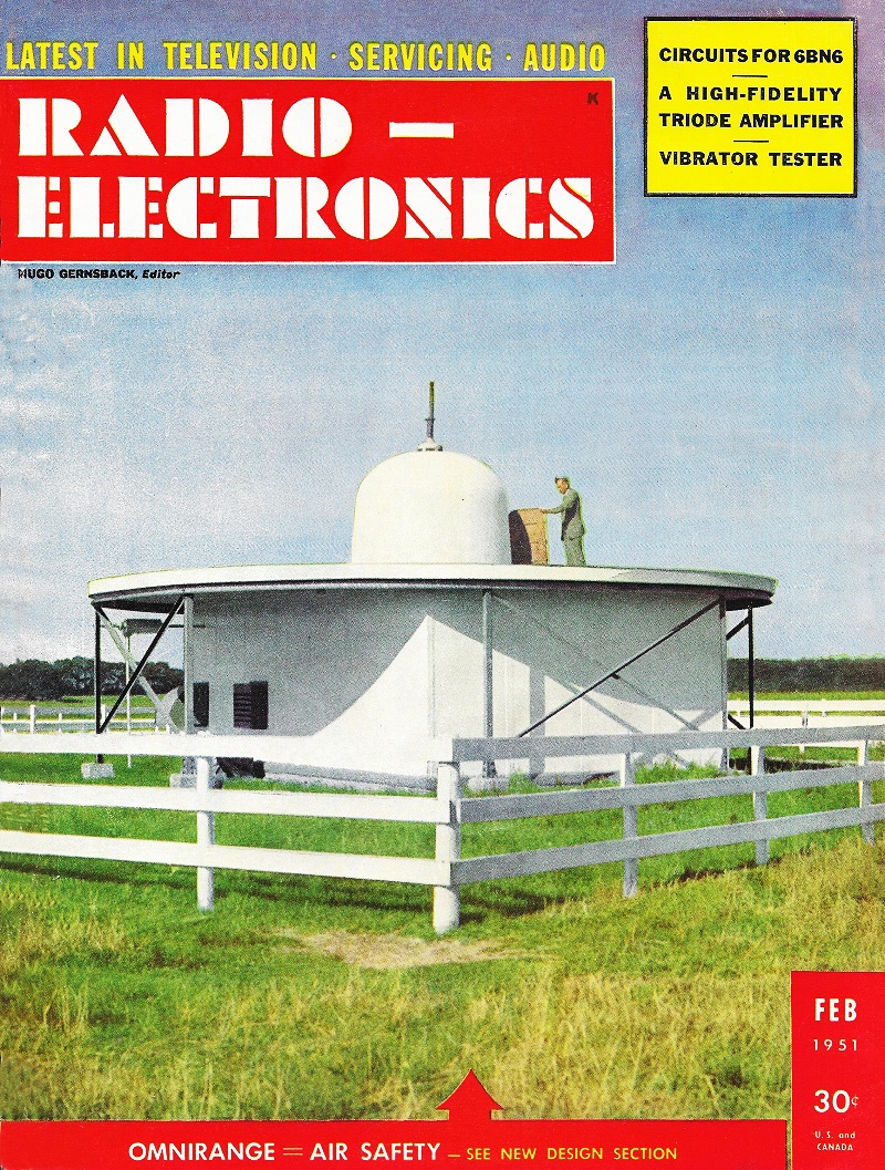
Omnirange = Air-Safety Cover Feature
 By
Samuel Freedman By
Samuel Freedman
Omnirange aircraft navigation will make air travel safe, dependable, and predictable
regardless of visibility, and volume of air traffic. A major innovation in air navigation,
the omnirange will require about fifteen years and $1,500,000,000 for installation
throughout the country.
The Civil Aeronautics Administration and equipment manufacturers are cooperating
to carry out the recommendations of the Radio Technical Committee and the Air Navigation
Development Board for this program. The Air Navigation Board is headed by representatives
from the CAA and the Army, Navy, and Air Forces. The Radio Technical Committee for
Aeronautics includes delegates from manufacturers, air transport associations, airlines,
 Enroute, the pilot can fly any desired track within range of the ground transmitters
strategically located throughout the United States. When approaching an airport
preparatory to landing, the aircraft aligns itself perfectly with the runways for
a v.h.f. localizer approach with the same equipment. The system uses the v.h.f.
communication receiver of the aircraft that also serves for two-way voice communication
with ground stations and other aircraft. The same receiver also receives voice signals
from the ground during a ground-controlled-approach landing operation. Enroute, the pilot can fly any desired track within range of the ground transmitters
strategically located throughout the United States. When approaching an airport
preparatory to landing, the aircraft aligns itself perfectly with the runways for
a v.h.f. localizer approach with the same equipment. The system uses the v.h.f.
communication receiver of the aircraft that also serves for two-way voice communication
with ground stations and other aircraft. The same receiver also receives voice signals
from the ground during a ground-controlled-approach landing operation.
The omnirange indicates direction because the v.h.f. receiver picks up signals
of a certain phase relationship for a given angle from the transmitter. A converter
unit transforms this phase relationship into an infinite number of courses with
respect to each ground station. The aircraft can use the omnirange no matter what
angle it bears and whatever its location. With the previous range systems on lower
frequencies, a plane could "fly the range" only along one of the four beams or legs
of a ground station. These are only 3 degrees wide. Instead of a total of 12 degrees
of range coverage in a total of 360 degrees, the omnirange covers 360 degrees for
every ground station.
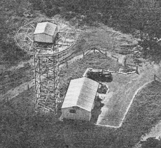
Fig. 1 - A typical omnirange station as the birds see it. The
antenna rotating" gear is in the shelter atop the mast.
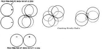
Fig. 2 - The two fields produced by the antenna pairs add together
to produce a rotating figure eight field pattern.
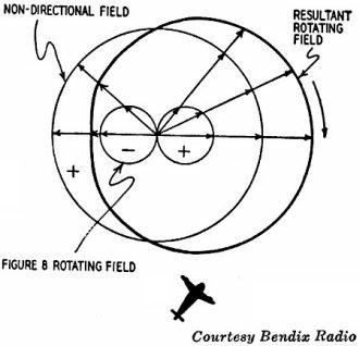
Fig. 3 - The resultant of the fixed and rotating fields is a
rotating cardioid.
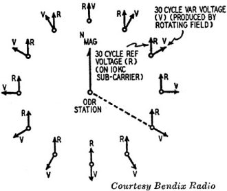
Fig. 4 - Each point on the compass has a different phase angle
between the reference (R) and variable (V) signals.
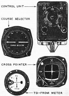
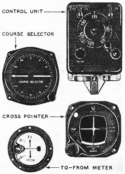
Fig. 5 - The pilot's control instruments.
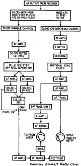
Fig. 6 - Block diagram of the converter.

Fig. 7 - Omnirange receiving equipment in miniature built for
small aircraft.
The Ground Station
Fig. 1 illustrates a typical ground omnirange station spotted to have minimum
distortion or error due to the topography of the earth. A circular ground plane
is atop the antenna tower. A housing transparent to radio signals protects the antennas.
The transmitter with its automatic emergency power supply is located in the house
adjacent to the antenna tower.
The ground omnirange transmitter radiates two radio signals which add together
to form a single signal at the receiving point, normally on an aircraft.
One of the two signals radiated is nondirectional. The other is a rotating field
comprising two figure-eight directive patterns at right angles to each other and
derived from a single signal source over two pairs of antennas. A split capacitor
rotated by a motor driven at 1,800 r.p.m. varies the voltage fed to the antenna
pairs at a sinusoidal rate of 30 cycles per second. The two figure-eight radiation
patterns add together at each instant through a full 360 degrees to form a new figure-eight
pattern as shown in Fig. 2. The non-directional field pattern from an additional
antenna is superimposed on this rotating figure eight to produce the resultant pattern
shown in Fig. 3. The sum of the rotating and nondirectional fields result in a rotating
cardioid radiation pattern. Because this field rotates, the signal strength at any
receiving point varies at the rate of 30 cycles per second (corresponding to the
motor rotation of 1,800 r.p.m.). It is called the variable (v) voltage. The nondirectional
antenna transmits another signal containing a fixed modulation or tone of 30 cycles
which is called the referenced (R) voltage. The variable voltage is compared with
the reference voltage to provide a measure of the bearing of the airborne omni-receiver
(the aircraft itself) from the ground station with respect to magnetic north or
zero bearing. A different phase angle exists between the reference and the variable
voltage for every change in direction between the air-borne receiver and the ground
omni-range transmitter as shown in Fig. 4.
The Aircraft Installation
Fig. 5 shows the controls or instruments used by the pilot in an aircraft for
omnirange operation.
1. Remote control unit for selecting the correct frequency of a tunable or present
receiver.
2. Course selector for the course that the pilot wishes to follow.
3. Cross-pointer meter or deviation indicator so pilot can determine what maneuvers
to make to stay on course.
4. To-from meter to indicate whether the station he is tuned to is toward or
from his location. He can work with a station behind as easily as with a station
ahead so long as the correct 180-degree side is used in laying out his course.
Besides these controls and instruments, the aircraft installation contains a
receiver, a converter unit, and power supplies. The receiver is a nine-tube AM superheterodyne
tunable from 108 to 135 mc.
Fig. 6 is a block diagram of the converter unit. It can function only on the
omnirange signals coming out of the v.h.f. receiver. This unit takes the complex
audio-frequency signal voltage from the receiver and converts it so that the bearing
of the receiving antenna (on the aircraft) can be determined with respect to the
transmitting antenna (at the ground omnirange station).
The a.f. signal consists of two independent components. One is the reference
channel signal. This is 9,960 cycles per second, frequency-modulated (changed in
frequency) at a 30-cycle-per-second rate to 480 cycles per second above and below
9,960. In practice, a round figure of 10 kilocycles is used in mentioning the 9,960-cycle
signal and it is referred to as the "10-kilocycle channel." After this signal passes
through a filter, a limiter provides a uniform signal by limiting the maximum values
which signals can attain. This is followed by a discriminator which converts changes
of frequency into changes in voltage. This derives the reference 30- cycle-per-second
voltage. Its phase is independent of the bearing of the transmitter.
The other one is 30 cycles per second (variable-channel signal) whose phase in
space at any given instant is a. function of the bearing from the transmitter. This
30-cycle variable amplitude modulation is in phase with 30-cycle frequency modulation
of the 10-kilocycle channel when the receiving antenna bears zero degrees from magnetic
north. At every other point around the ground transmitter, the two 30-cycle voltages
differ in phase by an amount up to 360 degrees, which can be read on the course
selector as a bearing to or from the omni-station.
In the block diagram (Fig. 6), the a.f. output signal from the receiver is filtered
to separate the 10-kc and 30-cycle components. A highpass filter passes the 10 kc
as indicated on the right side of the block diagram, while a lowpass filter passes
the 30 cycles as indicated on the left side of the same diagram.
On the 10-kc side, an additional 10-kc filter is provided after the discriminator
to eliminate residual 10 kc which might still be present at that point. It passes
through an audio-frequency amplifier and thence to another a.f. amplifier as well
as through a resistance-capacitance network to shift the phase approximately 90
electrical degrees to an audio amplifier. One amplifier goes through an a.f. transformer
to a watt-meter circuit comprising the cross-pointer meter while the other amplifier
goes through another a.f. transformer to a wattmeter circuit comprising the to-from
meter.
In the 30-cycle leg of Fig. 6, the out-put of the a.f, amplifier goes through
a lowpass filter and thence to a phase-splitting network which produces a 30-cycle
input to two a.f. amplifier tubes that are functioning 90 electrical degrees apart.
A circuit from each of the two tubes contains one primary of the course selector
(CUS SEL. PR. NO. 1 AND PR. No.2) while the secondary of the course selector (CUS
SEL. SEC) has a voltage induced in it whose phase depends on its angular setting
and whose magnitude is determined by the voltage at the input to the phase splitter.
In the PHASE-LOC (phase-localizer) switch position, the phase and amplitude of
the voltage applied to a tube are those required to give zero current in the cross-pointer
meter when the receiving antenna on the plane is in the center of the runway receiving
only reference voltage. On either side of on-course, a signal arrives through the
variable channel which is either in phase or 180 degrees out of phase with respect
to the reference voltage. The result is a motion of the needle to left or right
of center as the two signals are in or out of phase. The phase-localizer function,
designed for blind landing, is no longer in use.
Flying the Omnirange
U sing the equipment is simplicity itself. In the words of a very clearly written
CAA nontechnical booklet "Flying the Omnirange."
Let us suppose that the pilot decides to fly to a particular city. First, he
looks at a recent aeronautical chart, which shows the frequency and location of
each omnirange. He then selects an omnirange close to where he is going, and tunes
it in on the proper frequency. To be sure he has the correct range, he listens with
earphones to the identification, sent out either in Morse code or by voice recording.
Next. he turns his bearing selector until the vertical needle centers at the
bottom of the round dial. He glances at the to-from indicator to be sure the bearing
is to the omnirange. If it should be from, he merely turns the bearing selector
180 degrees, at which point the indication will become to.
All that he then has to do is to fly a course which will keep the vertical needle
centered. If it moves right, the pilot flies right to correct his course. If it
moves left, he turns the plane slightly left until the needle is centered.
That is all there is to it. If he keeps the needle centered, he will fly directly
over the omnirange. At that point. the to-from needle will flicker for a few seconds,
then change to a from indication. If the pilot desires to continue in the same direction,
he merely continues to keep the needle centered.
Nothing has been mentioned about correction for wind drift or correction for
magnetic variation because by using the omnirange there is no need for correction.
Keeping that vertical needle centered automatically "crabs" the plane into the wind
just the right amount to fly a straight-line course to the omnirange. Magnetic variation
is corrected in the omnirange itself - all its courses are in terms of the local
magnetic field.
New Developments
The omnirange program as described in this article is the first of three initial
phases of the postwar aviation navigational radio aid program. Many devices are
now in development and in production for early widespread adoption by major aircraft.
Simplified forms are being developed for private aircraft. The navigational computer,
also known as the R-Theta computer, uses two or more omnirange stations simultaneously
to provide constant and automatic fixes for an aircraft at all times. DME or distance-measuring
equipment operating on 1,000 megacycles is now under heavy initial production with
some $20,000,000 of equipment ordered for the ground stations. DME will show the
pilot the exact distance or number of miles he is to or from an omnirange, DME-equipped
ground point.
To make simplified, light, low-cost equipment available, the CAA has sponsored
initial procurement contracts to absorb the development cost so that plane owners
can buy such equipment on the basis of production cost alone. In competitive bidding,
such a contract was awarded by CAA to the National Aeronautical Corp. of Ambler,
Pa., which has developed the equipment shown in Fig. 7. The components are:
1. Receiver using seven tubes and continuously tunable from 108 to 122 mc as
required for omni- and two-way radio reception. The weight is 2 pounds.
2. Transmitter for two-way voice communication. It weighs 22 ounces, has six
crystal-controlled channels, and an output of 3/4, watt.
3. Omni-converter.
Other manufacturers are also developing receiving equipment for putting the entire
system into one compact cabinet or panel for dash mounting. In the costlier and
larger systems, up to 280 crystal-controlled, automatically selected channels can
be selected for communication and navigation.
Whenever a ground omnirange station is so situated with respect to terrain conditions
that errors exceeding 3 degrees take place in aircraft, the CAA has made local constructional
changes or even moved the entire omnirange station to a more reliable location.
The need to do this has been minimized by extensive field tests with portable omni-range
ground stations in advance.
Posted February 18, 2022
|