|
August 1963 Radio-Electronics
 [Table of Contents] [Table of Contents]
Wax nostalgic about and learn from the history of early electronics.
See articles from Radio-Electronics,
published 1930-1988. All copyrights hereby acknowledged.
|
Take note of the unique
Smith Chart superimposed on the original soothsayer's crystal ball in this "Mysticism
in Output Matching" article, which appeared in Radio-Electronics magazine.
That is a rendition of the 3D Smith Chart*
as developed by Dr. Andrei A. Muller and his team. Having only been recently
created, the 3D Smith Chart was not around in 1963 when Herbert Ravenswood published
his piece. In fact, although
Phillip H. Smith's
original Smith Chart had been around since 1939, it does not appear anywhere in
the article. Mr. Ravenswood addresses the important difference between maximum power transfer and maximum efficiency of power transfer.
Audio frequencies are specifically addressed (which might explain the absence of
a Smith Chart) with regard to interfacing the output of a power amplifier to a
speaker, but the concept is similar when dealing with RF frequencies. As with
many articles on matching, the reactive part is not dealt with, so really it is
an article on resistance matching, not impedance matching (unless there happens
to be no reactive component).
Mysticism in Output Matching
 What we learned in the school books is true,
but not necessarily relevant. What we learned in the school books is true,
but not necessarily relevant.
by Herbert A. Ravenswood
In the article "Taking the Mysticism Out of Matching," July, 1961, we considered
"input" matching: from some kind of transducer-microphone, pickup or tape head-to
a tube or transistor input, or from a preamp output to a main amp input. In all
cases, we were mostly concerned with adequate voltage or current level and freedom
from non-linear or frequency-response distortion.
Output matching is often concerned with maximum power transfer. Thus, at first
sight, it would seem to call for the theoretical or schoolbook ideal: load impedance
equal to source impedance. To get this straight, the first thing we have to do is
distinguish between maximum power transfer and maximum efficiency of power transfer.
They are not the same thing. Let's illustrate.
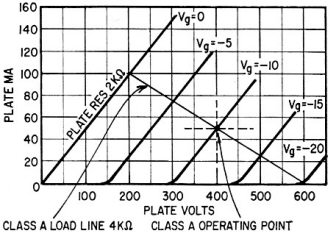
Fig. 1 - Class-A operation, ideal triode.
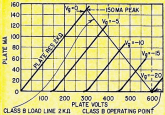
Fig. 2 - Fig. 1 Triode in class B.
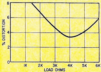
Fig. 3 - Distortion-load curves like this can be quite meaningless.
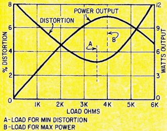
Fig. 4 - This is a useful type of curve.
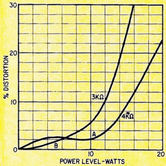
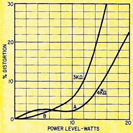
Fig. 5 - Distortion figures differ with small changes in load
value. Note different curves for 3,000 and 4,000 ohms.
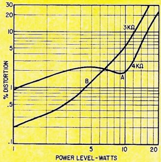
Fig. 6 - A more truthful curve is one plotted on log paper instead
of linear. This is a re-plot of Fig. 5.
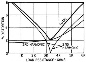
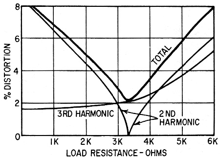
Fig. 7 - How the distortion varies with load in a typical single-ended
pentode.

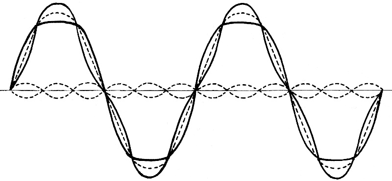
Fig. 8 - Third-harmonic distortion can have two effects on the
waveform; dashed line is fundamental, solid lines show the two effects of third
harmonic.
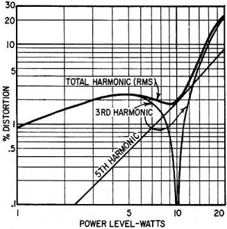
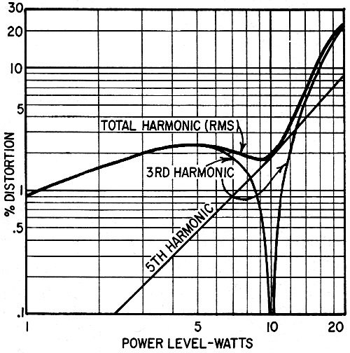
Fig. 9 - How curve A in Fig. 6 is made up. Below 10 watts, third harmonic tends
to point the wave; above 10 watts, it rounds it. At 10 watts there is no third harmonic
and all distortion is fifth harmonic.
Assume we have a supply, from a battery, generator or alternator - it doesn't
matter. It gives 110 volts open-circuit and has an internal resistance of 5 ohms.
According to the ideal matching theory, the load should also be 5 ohms, making 10
ohms total. The current will be 110/10 = 11 amps. The power transfer will be 55
volts (the voltage across the load) x 11 amps, or 605 watts.
If we use a 6-ohm load, the current will be 110/11 = 10 amps, the load voltage
60, and the power transfer 600 watts. With a 4-ohm load, current will be 110/9 =
12.2 amps, load voltage 48.9 and power transfer 597.5 watts. This proves that a
5-ohm load yields maximum power transfer - 605 watts.
But to get the power into the load, additional power is lost in the battery,
generator or alternator. With a 5-ohm load, for 605 watts output, 605 watts is lost
internally; an efficiency of 50%. With a 6-ohm load, the internal voltage drop is
50, the current 10 amps, the internal power loss 500 watts. Of a total of 1,100
watts (instead of 1,210 watts with a 5-ohm load), 600 reach the 6-ohm load; an efficiency
of 54.5%.
With a 4-ohm load, for 597.5 watts output, the internal volt drop is 61.1, the
current 12.2 amps, the internal power loss 747 watts. Of a total of 1,344.5 watts,
597.5 reach the 4-ohm load; an efficiency of 44.4%.
Now let's figure out that happens with a 50-ohm load: total resistance 55 ohms,
current 2 amps; voltage across load, 100, internal drop, 10 volts; power in load,
200 watts; internal, loss 20 watts; total power 220 watts; efficiency 91%.
So, by being content with about one-third of the maximum power, the efficiency
rises from 50% to over 90%. Regardless of how you are billed for it, what has to
be bought is the total power, not the power output. This is another good reason
(fire hazard is the first) why it's not good to load your supply so it drops from
110 volts to 55!
Why do we match?
We worked through that just to show that the academic ideal doesn't often work
out for practical purposes (even in power engineering). But now to audio and kindred
subjects: this introduces many more factors. First we'll list them, then explain
them.
In the simple power case, we had two possible objectives: matching for maximum
power, or for maximum power-transfer efficiency. In audio outputs we have at least
four possible objectives, any one of which may be most important in individual cases,
with the others having either subsidiary importance or being unimportant. These
four are:
When we've digested these basic different objectives, the matter can be approached
from two viewpoints: that of the tube or transistor, and that of the load. This
has caused much extra confusion since feedback became almost universal.
Finally, there is the complication of multiple operation. So far, we have been
concerned with only one source - a tube or transistor output stage-feeding one load;
matters are complicated when either is shared. Such sharing may be between either
the source (two or more tubes, or their screens as well as their plates) or the
load (feeding more than one loudspeaker, possibly at different power levels) or
sometimes both.
Small wonder the uninitiated - and some engineers - get confused about matching.
To try and simplify matters, let's take up each of the points, one at a time.
Maximum power
This is the case where we have one or two output tubes or transistors, with a maximum dissipation before they "blow," and we want to get the maximum
audio power output from them. In this problem we are not pri-marily concerned with
grid input volts or base input current. Whatever is needed we can get, somehow;
but we mustn't exceed the tube or transistor ratings.
Assume an "ideal" triode tube (one with perfect curves, Fig. 1) is operated class-A,
with 400 volts at 50 ma static plate current. This represents its maximum dissipation
of 20 watts. It has a plate resistance of 2,000 ohms. Optimum load-the one for maximum
relatively undistorted power - will be 4,000 ohms. The peak audio voltage and current
in this load will be 200 volts 50 ma, a peak power of 10 watts, or an rms rating
of 5 watts. This is 25% efficiency.
We can improve this by what is called class-B working, or a part-way measure
called class AB. We will assume a perfect class B. The plate voltage is now made
600, operating current (theoretically) zero (Fig. 2). Each of two tubes delivers
power for half the output waveform, with a peak value of 300 volts 150 ma, using
a load equal to the plate resistance of 2,000 ohms. This is a peak audio power of
45 watts, with a peak dissipation of 45 watts.
On a sine wave, the average dissipation during each half-cycle, in this mode
of operation, is 77.5% of maximum; over the full cycle (the other half is inactive)
it is 38.75%. So the average dissipation per tube, at maximum power, is 17.4 watts
- well within the rated 20. The audio power from two tubes, rms rating, is 22.5
watts, as against 10 watts from two tubes working class A.
We'll come back to what impedances mean in the output transformer for these two
cases later on. We could pursue this matter of maximum power output within maximum
power dissipation through pentodes, transistors and other devices, but this illustrates
a couple of typical relationships.
Pentode and transistor matching does not introduce an "ideal" relationship between
source and load impedance, for the simple reason that the theoretical ideal plate
or collector resistance is infinity, while the optimum load resistance is always
finite and is governed by things other than its relation to a theoretically infinite
quantity.
In a theoretically ideal pentode, the plate current-voltage curves would be horizontal
lines above the "knee," signifying infinite plate resistance. The choice of load
resistance is determined by finding a load line that will give the biggest combination
of voltage and current swing, to make audio power, without using an area of the
curves that goes over the permitted dissipation for the tube(s).
Minimum distortion
When you take distortion into account, the matching problem becomes involved.
A curve that plots distortion against load value (Fig. 3) is meaningless unless
more details are given. At what level of power output is the curve taken? Is the
power kept constant as load value is changed? Such a curve can be taken in a variety
of ways; unless you know how it was taken, it is of little value to you.
One method is to set the level at each load value to represent the same power
output, which should be stated. The curve may be quite different if the level is
changed. Another method is to set the level at each load value to the maximum output
before clipping - itself a form of distortion - commences. Information obtained
from this method does not mean anything unless the curve is accompanied by a corresponding
curve for power (Fig. 4).
The thing that can be misleading about any matching-for-minimum-distortion presentation
is that distortion changes with level in different ways for different load values
(Fig. 5). So the choice of load value depends on what you consider "minimum distortion."
One value will produce minimum distortion at maximum output; another will maintain
minimum distortion over a range of lower levels. These values are not usually widely
different, so the distinction may be more academic than practical in most instances.
But the way you plot distortion, using log or linear scales, can make a difference
to what it looks like (Fig. 6). Note that the low-level distortion now looks more
important.
Why do we have these differences in distortion characteristic? It is well known
that a single pentode output stage produces a distortion characteristic, as load
value is changed, with a minimum value where the second harmonic disappears (Fig.
7). In a push-pull circuit, properly balanced, there is no second harmonic. But
the third harmonic can have two effects; it may either "sharpen" or "round" the
waveform (Fig. 8). In many push-pull circuits employing pentodes, both forms of
third-harmonic distortion occur at different levels, feeding the same load, and
there is also a fifth-harmonic component (Fig. 9).
Between the variables of load value and level, distortion can change in a complicated
fashion. That's assuming the load is just a simple resistance. When you include
the reactance elements in loudspeaker impedances, distortion is quite unpredictable.
Maximum gain
This aspect of matching comes closest to what we learned in school. In this case,
what we said earlier about somehow being able to get whatever grid volts or base
current we need is not the case. An example is the one-tube amplifier used in some
low-priced phonographs.
The grid swing is limited to the output from the ceramic or crystal pick-up cartridge.
We want the maximum output power that a single pentode stage will produce from this
grid input. The load required will differ from what we had when we were matching
for either maximum undistorted power or minimum distortion. It will be closer to
the academic ideal than the value selected for other purposes.
Matching for this condition will not usually achieve either maximum power, for
the tube or tubes are capable, or minimum distortion. But it does produce the loudest
sound for the available grid input from the pickup cartridge. If a bigger grid swing
were available, a different operating point and load resistance give us greater
output power, lower distortion or both.
Thus we see that choice of load value in output matching has a number of different
possible objectives - or combinations of them - to meet. No single optimum load
will suit all these objectives. This has been the reason for some confusion. Different
values may have been published for the same tubes, without stating for what parameters
the load is optimized, or the parameters may have been stated but overlooked because
the reader had the notion "optimum load" had some absolute meaning. We hope this
discussion will clarify this matter, so you will no longer be looking for an absolute
optimum, and will be curious enough to find out what parameters governed the choice:
maximum power output, minimum distortion or maximum gain.
The fourth point we listed introduces some further aspects that are quite independent
of those we have just discussed. Why is the resistance, as determined by a quantity
called damping factor, at an output terminal plainly marked 16 ohms, only 0.1 ohm?
How can one pair of terminals at the same time have two such different impedances?
This and other questions, particularly relating to the effect of feedback on this
kind of situation, and some complications that arise with different impedance loudspeakers
being connected to different amplifier taps than those bearing the right "ohmage"
label, are a complete story in themselves, and will be discussed in a later article.
* See my 2017 review of the
3D Smith Chart.
Posted June 13, 2023
|