|
July 1960 Radio-Electronics
 [Table of Contents] [Table of Contents]
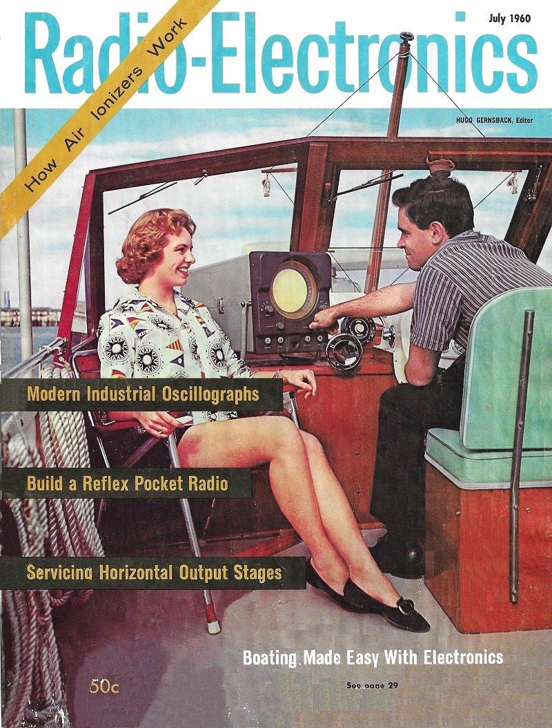
Wax nostalgic about and learn from the history of early electronics.
See articles from Radio-Electronics,
published 1930-1988. All copyrights hereby acknowledged.
|
In this second installment
in his "Principles of Modern Radar" series in Radio-Electronics
magazine, author Jordan McQuay discusses pulse-Doppler radar, which exploits the
frequency shift of moving targets to discriminate against fixed objects. The
ability to separate fixed from moving targets is generally more difficult are
the moving target gets closer to the fixed object(s), such as when near the
ground during take-off and landing, and when mountains are nearby in the
background. Clutter cancellation can and is also accomplished by comparing radar
return signals to previous returns and subtracting the two so that only the
newer signal survives for display on the scope (plan position indicator, or
PPI). That is how the AN/MPN-14 (13)
radar system I worked in the in the U.S. Air Force worked.
Principles of Modern
Radar - Part I was published in the July 1960 issue.
Principles of Modern Radar - Part II

Part II - Pulse-Doppler systems eliminate many of the disadvantages
of other radar systems in detecting and indicating moving targets.
By Jordan McQuay
The two basic kinds of radar discussed in the first part of this series were
the pulse-modulated or PM and the frequency-modulated or FM. Although both provide
accurate range and azimuth data, they depend on targets of fairly large size which
do not move rapidly with respect to the range.
For example, PM radar is excellent for long-range detection and tracking of missiles
and satellites in outer space. Although such targets may actually be traveling at
high speeds, their rate of movement is not too consequential when compared to range
distances of thousands of miles.
At very short ranges, ground-based PM and FM radar is ineffective in locating
targets on or just above the ground - particularly when they are moving over the
earth's surface.
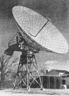
Antenna of giant PM radar used to detect and track missiles and
satellites.
- US Army
A long-persistence PPI (plan position indicator) scope provides, with successive
sweeps of the radar antenna, a series of repeating echoes from moving as well as
fixed targets. Close scrutiny of slight changes in the position of these echoes
on the scope screen gives some indication of movements of any target. But there
is no highly accurate indication of moving targets on the PPI scope of a PM radar.
It is even more difficult to see target echoes when they are submerged or partially
covered up by echoes from fixed objects on the terrain.
This important requirement is met by a third kind of radar. Combining certain
features of both the PM and FM, it is known as pulse-Doppler or PD radar because
it uses the Doppler effect effectively.
The Doppler effect was named after the man who discovered it. It is simply an
apparent change of frequency of any received signal by a moving object (the object
can be stationary and the signal source moving). A common example of this is the
change in pitch of a whistle or bell on a train as it goes past a listener. The
passengers on the train also experience this effect when listening to gate-crossing
bells and such. The effect is not limited to sound or radio (or radar) signals:
the light from a moving star seems to change in frequency (color). The light shifts
toward the red region of the spectrum when the star recedes from us and toward the
violet region when it approaches us.
Radar signals from a moving target are doubly affected by this effect. The target
receives a signal that is changed in frequency and then reflects (or effectively
retransmits) it to the original source. Since the target is moving with respect
to the source, the frequency of the signal is changed again.
A PD radar can detect and locate all objects and targets within range - it sorts
out moving targets with special data-processing circuitry and displays these and
only these echoes on an indicator. A PD radar is sometimes called an MTI or moving-target
indicator.
A single and important advantage of PD radar is that it defines moving objects
and targets clearly at greater ranges - regardless of ground clutter and echoes
from fixed objects or targets - than is possible with any other kind of radar.
Although developed primarily for military surveillance, PD radar will ultimately
find commercial use for similar specialized applications.
Radar Components
A PD radar (see block diagram) is similar in many ways to the PM type. The principal
difference is in the receiving circuit.
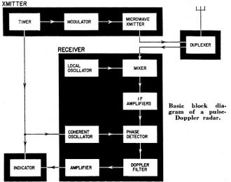
Basic block diagram of a pulse-Doppler radar.
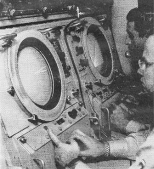
PPI scope of long-range surveillance PM radar displays only approximate
data on moving targets.
- Hughes Aircraft
At an operating frequency of several hundred or sometimes thousand megacycles,
the radar transmitter sends out pulses of microwave energy. These are directed by
the antenna system toward the area being searched or scanned.
The number of such pulses per second - usually about 5,000 - is called the prf
(pulse recurrence frequency). The duration of each RF pulse is extremely short -
less than 1 μsec - to allow time for reflected echoes from objects or targets
to be received by the PD radar.
The prf and the pulse duration are both controlled by the timer. It also provides
trigger voltages to synchronize operation of the transmitter, receiver, indicator
and other components of the radar system.
A duplexer - or TR switch - permits use of a single antenna for both transmitting
and receiving.
Objects and targets within range of the radar and reached by the very narrow
RF beam from the antenna will reflect very weak echoes - usually less than 1 μv
in strength. These reflected echoes are picked up by the antenna and pass directly
through the duplexer to the microwave receiver, which is broadly tuned to the same
operating frequency as the radar transmitter.
In the receiver, echo signals are mixed with a local-oscillator signal to produce
an if of 30 mc (sometimes 60 mc) , which then passes through several stages of broad-band
(if) amplification. Automatic circuits in the receiver provide for frequency control
of the local oscillator and for gain control of the incoming echo signals.
At the same time, a coherent oscillator - actually a second local oscillator
- is operating continuously at the if (30 mc or 60 mc). It produces if control signals
that have a fixed phase relationship (or phase coherence) with the if echo signals.
Both signals - if control and echo - are applied to a phase detector. It combines
them into video signals having a polarity determined by the phase difference between
the. control signals and the echo signals.
Echoes received from stationary objects and targets produce video signals (at
the output of the phase detector) with a fixed polarity. Echoes from moving targets
produce video signals that change in polarity at a frequency proportional to the
rate of movement of the objects or targets.
To sort out and eliminate the video signals of fixed polarity (from fixed targets),
the output of the phase detector is applied to a Doppler filter. This discriminates
against all video signals of fixed polarity, but passes all video signals that represent
moving targets. The Doppler filter is a complicated device. Something like a bandpass
filter, that is extremely sensitive to signals of fixed polarity.
After suitable amplification, the video output of the Doppler filter can be utilized
or displayed in several ways.
The video signals can be used to modulate an audio amplifier which produces an
audible tone whenever the PD radar detects a moving object or target. A headphone
enables an operator to zero in on such targets, and thus provides data for manual
plotting of range and azimuth. The frequency of the audio tone is about 30 cycles
per second for each mile-per-hour motion of a target. The faster the movement, the
higher the pitch of the audio tone.
The same video signals can be used to activate low-frequency voltmeters or other
similar indicating devices. Or they can be fed to a frequency-indicating meter or
graph calibrated in miles per hour (commonly used to detect speeding automobiles).
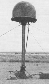
Antenna system for medium-range military surveillance radar.
Radiating element rotates beneath plastic housing. - US Army
Some types of PD radar use a PPI scope with a special intensifying circuit. Amplified
video signals from the Doppler filter control a threshold detector. This, in turn,
modulates or controls a low-voltage oscillator that intensifies a portion of the
PPI scope in accordance with the video signal. Range and azimuth of each moving
target are determined in the conventional manner for PPI scopes. But in this application,
there are no interfering fixed echoes or ground clutter from fixed targets visible
on the radar scope. Only echoes from moving targets are visible on the scope face.
Other kinds of scopes may be used similarly, but require special locally controlled
intensifying circuits.
Memory systems
Echo signals exhibiting Doppler-shift frequencies can be measured rapidly only
with some type of memory system that accurately "remembers" the broadcast frequency
of the transmitter and compares it quickly with the frequency of the echo signals.
The memory system just described is used for most ground-based PD radar where
there is no appreciable change in frequency between successive signals. For this
reason, it is called a coherent or "locked" system.
In the noncoherent system, a portion of the transmitted pulse power is stored
electronically for comparison with echo signals. This comparison utilizes an echo
signal reflected by a fairly large stationary target. Such an echo signal, which
is not changing in frequency, is fed into a time-delay circuit prior to comparison
with echo signals from moving objects and targets.
One example of a noncoherent PD radar is an airborne "side-looking" radar that
scans downward, alternately, from each side of low-flying aircraft. Echo signals
from stationary objects provide the reference required for frequency comparison.
The radar provides a continuous picture map of the ground, about 30 miles in width,
as the plane flies along. For low-speed low-altitude aircraft, this provides an
intimate view of all moving objects on the earth below it.
For comparable target reporting, PD radar, utilizing either type of memory system,
is generally more effective than the PM or FM types.
The performance of PD radar is evaluated according to two parameters. One is
the minimum strength of echo signal from a moving target that can be detected in
the absence of any fixed objects. The second factor - called sub-clutter visibility
- is the ratio of the maximum strength of echo signal from a fixed target to the
minimum strength of echo signal obtained from a moving target.
Posted July 11, 2023
|