|
December 1955 Radio-Electronics
 [Table of Contents] [Table of Contents]
Wax nostalgic about and learn from the history of early electronics.
See articles from Radio-Electronics,
published 1930-1988. All copyrights hereby acknowledged.
|
I swear when I perused
the December 1955 issue of Radio-Electronics there was a good reason
that I tagged this "Your Receiver as an Audio Generator" article for posting, but I'll be danged if the motivation for it is obvious now. There's
nothing undeserving about the subject from the perspective of a reader back in
the day when test equipment could be hard and/or expensive to come by. In fact,
as with many of the articles selected this one demonstrates the old
maxim about how necessity is the mother of invention. No less an authority on
the value of being able to cobble up test equipment from magazine articles and a
box of spare parts than Mac McGregor, proprietor of
Mac's Radio Service Shop, promotes the practice as an essential skill. Even
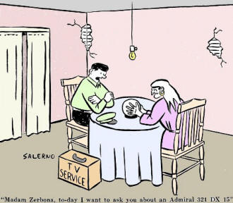
if you don't find the article useful, at least there's an electronics-related
comic on the page to entertain you.
Need a tone generator for occasional use in the shack? If so,
try this simple trick
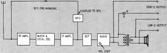
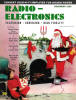
Block diagram of a receiver set up to operate as an audio oscillator.
By Fred Lingel, W2ZGY
A shortwave receiver can be used as an audio-frequency signal generator for modulation
and other audio checks merely by feeding some of the b.f.o. second harmonic back
to the antenna. To do this the beat-frequency oscillator output is capacitively
coupled to the antenna connection of the receiver. This can be done either by wrapping
a section of hookup wire around the tube or by inserting an insulated section of
hookup wire into the oscillator coil can. If greater coupling is necessary because
of low signal output, the antenna can be coupled directly to the plate pin of the
b.f.o. through a 100-μμf capacitor. Turning on the b.f.o. or CW oscillator
and tuning to or near the b.f.o. second harmonic produces a variable-frequency audio
signal in the speaker.
The principle of operation is: If the i.f. of the receiver is 453 kc, and the
b.f.o. is set at zero beat then the b.f.o. will generally have a very strong second
harmonic at 906 kc. By coupling this signal back to the antenna terminal and tuning
the receiver to around 906 kc (in the broadcast band) a signal will be heard in
the loudspeaker. The frequency of this signal can be adjusted from near 0 to 20
kc or higher, depending upon the receiver components, the loudspeaker, etc. This
can be done by varying either the main tuning dial or the CW pitch control.
 If the main tuning dial is used to adjust the signal, the approximate frequency
can be determined from the dial markings of the receiver. For example, if zero beat
is obtained at exactly 906 kc on the receiver tuning dial, then at the 911-kc mark
the output will be 5,000 cycles, at 916 kc it will be 10,000 cycles, etc. This is
based on a 453-kc i.f., a second harmonic at 906 kc, the receiver local oscillator
operating on the high side of the input signal and the CW pitch control at zero. If the main tuning dial is used to adjust the signal, the approximate frequency
can be determined from the dial markings of the receiver. For example, if zero beat
is obtained at exactly 906 kc on the receiver tuning dial, then at the 911-kc mark
the output will be 5,000 cycles, at 916 kc it will be 10,000 cycles, etc. This is
based on a 453-kc i.f., a second harmonic at 906 kc, the receiver local oscillator
operating on the high side of the input signal and the CW pitch control at zero.
Similar frequencies will also be obtained when the receiver dial is tuned to
the low side of 906 kc, that is 0, 1,000, 2,000 and 3,000 cycles of audio will also
be obtained at the 906-, 905-, 904- and 903-kc dial settings.
This system provides an audio voltage at a low impedance, around 5 ohms, from
across the speaker coil. In addition, a high impedance, around 5,000 ohms, through
a 2-μf external coupling capacitor can be obtained from the plate of the output
tube. In addition to these two output impedances, an audio signal can be obtained
directly from the loudspeaker. In this way sound may be applied to a microphone
for an over-all response check of the audio system. The receiver, arranged as an
audio signal generator, is shown in the block diagram.
The volume control of the receiver acts as a level control. An external rectifier
type a.c. voltmeter can be connected across the output to measure the approximate
amplitude of a.c. voltage for audio checks. Most multimeters set to read a.c. output
voltages on a lower voltage range will give a fair measure of the a.c. voltage.
Higher-voltage a.c. ranges may be considerably in error because of the distributed-capacitance
shunt effect across the multiplier resistors. This is especially noticeable on the
5,000-ohm-per-volt (and higher) a.c. rectifier voltmeters. If a v.t.v.m. is used
to check the audio system, it should be realized that these are generally peak-reading
instruments and distortion in the waveform may cause considerable error in output
level readings.
This generator has served very well for modulation checks in my amateur station.
While it is not a final answer by any means, it is certainly a lot better than trying
to whistle a prolonged 2,000-cycle constant-level note. Too, you can send code to
the Jr. Op with a key across the b.f.o. switch.
Posted November 30, 2020
|