|
August 1969 Radio-Electronics
 [Table of Contents] [Table of Contents]
Wax nostalgic about and learn from the history of early electronics.
See articles from Radio-Electronics,
published 1930-1988. All copyrights hereby acknowledged.
|
When transistors finally
began operating in the hundreds of MHz in the 1960s, power handling was still relatively
low, and the devices could be damaged or destroyed by a large signal, particularly,
as cited in this "RF Circuit Protection" article from a 1969 issue of Radio-Electronics
magazine, when the relay switching the antenna between transmit and receive does
not have adequate isolation. Another scenario is operating in a close-quarters group
of radio operators at a Hamfest, emergency communications post, etc. Over time,
more robust transistors were designed, and some had built-in protection diodes.
As gate sizes shrank, vulnerability to
electrostatic discharge (ESD) reared its ugly head in RF integrated circuits
like frontend modules and switches. During the early 2000s, IC makers like
RF Micro Devices (now Qorvo),
Skyworks (spun off from Alpha Industries),
Renesas, and a few others, were in a
race to conform to the de facto ESD standards for
human body model (HBM) and
machine model (MM, not used any more) survivability. The challenge was not so
much being able to protect the I/O pins, but the amount of wafer real estate required
to accommodate the protection diodes and/or transistors.
RF Circuit Protection

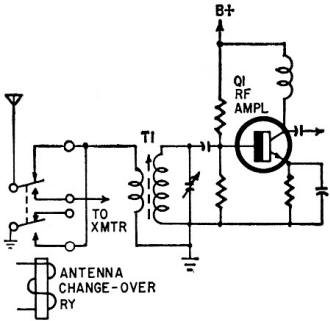
Fig. 1 - Unprotected RF front end.

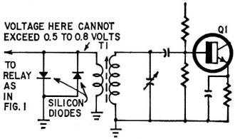
fig. 2- RF front end protected with back-to-back diodes.
By Irwin Math
In many transistorized converters and high-frequency front ends, especially those
designed for mobile two-way radio and amateur applications, a potential condition
exists which could easily destroy the input transistor. Figure 1 is a schematic
of such a front end. When the transmitter is turned on the antenna changeover relay
is supposed to short the receiver input to ground. Even if the relay does make excellent
contact, a small signal is usually induced in the primary of the receiver's rf transformer,
(T1) especially if the operating frequency is in the uhf region.
If, on the other hand, the relay makes poor contact, a substantially large signal
can appear at this coil. Since T1 is a step-up transformer (usually 50Ω to
200Ω or so) approximately twice the primary voltage appears in the secondary
between the base and emitter of Q1. Assuming the transmitter puts out only 10 watts
into a 50Ω antenna, we have about 60 volts peak-to-peak at the antenna. Unless
that shorting contact is pretty good, we can say goodbye to Q1, which can only take
a maximum of 3-4 volts between base and emitter. Let's say that everything is working
properly however. This condition still exists.
When S1 switches from transmit to receive, there is an instant when the receiver
line is not shorted and the transmitter is still delivering power. This is due to
the fact that the electrolytics in the transmitter take some time to discharge,
therefore even if the transmitter supplies power for only 50 milliseconds (0.05
sec) after the relay opens, Q1 will still be destroyed by the high-voltage pulse
produced.
A simple method for protecting against accidental overloads of this nature is
given in Fig. 2. Two silicon switching diodes are connected in parallel opposing
across the input coil. These diodes exhibit extremely high forward resistances when
the voltage applied to them is below 0.5 to 0.8 volt. Any higher voltage causes
the diodes to conduct and the forward resistance drops to a couple of ohms. In this
manner, the input voltage to the rf amplifier is always kept to a safe level. Any
medium- to fast-speed silicon switching diodes can be used in this circuit. Germanium
diodes do not have the same low-voltage characteristics and will not work.
Posted August 21, 2023
|


