|
July 1960 Radio-Electronics
 [Table of Contents] [Table of Contents]
Wax nostalgic about and learn from the history of early electronics.
See articles from Radio-Electronics,
published 1930-1988. All copyrights hereby acknowledged.
|
If I have ever heard of a
"trigistor" (aka "dynaquad") before seeing it in the 1960 Radio-Electronics
magazine article, I don't remember it. It is a p−n−p−n silicon switch device that
is essentially the same as a thyristor in that conduction can be turned on or off
with separate control signals that can be removed once the switching action is initiated.
According to the Wikipedia entry for the
thyristor, it was first introduced
in 1956, not so long before this article. The Howard W. Sams
Transistor Circuit Manual, 1961, by Allan Lytel provides information
on not just the "trigistor," but also the "binistor," another bistable on/off silicon
switch. Other process control devices such as unijunction transistors, avalanche
diodes, silicon controlled rectifiers (SCRs), and cryostats (used for temperature
control) are discussed. The electronics industry was in the early stage of transition
from vacuum tubes to solid state devices.
Semiconductors for Industrial Controls
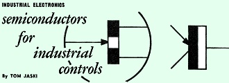
Transistors, Unijunction transistors, avalanche diodes, Trigistors,
silicon controlled rectifiers and cryostats are all usable as static switches.
By Tom Jaski
In the two previous articles we discussed magnetic amplifiers and the special
control systems based on logic units developed from them. Much newer, and therefore
not as widely applied, is an entirely different system, based on transistors.
To build logic units we need some kind of a switch or device with two states,
conducting and nonconducting. A transistor fits in because we can recognize in its
operation two greatly differing states, one of very high resistance and one of very
low resistance: These two operating points are shown in Fig. 1. The transistor is
off at A and on at B. Essentially, the only difference in circuit values responsible
for these two states is the base current.
The quality of a transistor switch depends on how well we can reduce leakage
current from collector to emitter. By providing a small amount of reverse bias,
we can keep the transistor cut off. Fig. 2 shows the basic circuit of a transistor
switch with reverse bias applied. There are other possible circuits, but the engineers
who build industrial control systems consider reliability one of their most important
criteria, and careful analysis has shown that the common-emitter switching circuit
is the most reliable arrangement. Fig. 2 is the basis of a fundamental logic unit.
Apply a signal to the input and the transistor presents a virtual short to its output
(there is no output signal). This forms a logic unit we call a NOT circuit. If we
add several inputs to this circuit so a signal applied to anyone of them saturates
the transistor, we can say that neither a signal on 1 nor a signal on 2 will provide
an output, and we call this a NOR unit (any input prevents an output). An entire
control system with logic units can be based on this NOR circuit. We can, of course,
include one, two or more inputs, so long as we isolate them from each other with
resistors as shown in Fig. 3. Generally speaking, we reach a limit when we have
about 10 inputs.
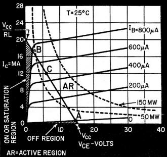
Fig. 1 - Typical common-emitter characteristics of a transistor.
Note the on and off regions.
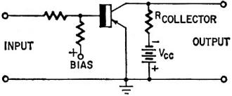
Fig. 2 - Basic transistor switching circuit.
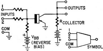
Fig. 3 - Basic transistor NOR circuit and symbol.
Transistor Logic Units
Fig. 4 shows the logic units we can build. Fig. 4-a is a simple NOT unit, which
is the NOR with a single input. If we make the units all alike and ignore some inputs,
we waste some resistors, but the fact that we are making only one kind means that
the units can be mass-produced. Fig. 4-b is the two-input NOR, and 4-c is an AND
unit made up of two NOT units and one NOR unit. As. long as no signal is applied
to one of the NOT units, there is an output that prevents an output from the NOR
unit. Both I and II must have an input to get an output from III.
Fig. 4-d shows a flip-flop which we can use as a MEMORY unit. Here we use a couple
of 2-input NOR circuits, with the input of each one connected to the output of the
other.
To examine the flip-flop's operation, let's start with a nonconducting state
for both transistors, and no power on. As soon as power is applied, both transistors
start to produce an output. But one will be very slightly faster, and its output
will saturate the other and keep it saturated. So one stable state is intrinsic
to the circuit. Assume that I is conducting, and II is nonconducting. If we apply
a signal at input 2, transistor II saturates and its output stops, cutting off I.
Alternate pulses at inputs 1 and 2 reverse the state of the memory unit at each
pulse.
Fig. 4-e is an OR circuit made from a NOR unit followed by a NOT unit. A signal
at either A or B keeps I turned off and no signal is applied to the NOT unit, so
we get an output at C. But with no signal on A or B we get an output from I which
cuts off the NOT unit and prevents an output at C.
Another logic unit we have not previously encountered, but possible with the
NOR system, is shown in Fig. 4-f. This is constructed from one NOT and one NOR unit.
As long as there is no signal on the control, there will be an output from II but,
as soon as a signal is applied to the control input, the output is "inhibited".
This INHIBITING GATE is a very useful tool for connecting, disconnecting and controlling.
Time delay is important in logic systems. Fig. 4-g shows a time delay built around
two NOR units. Normally unit I is cut off, producing an output which keeps II saturated.
If we apply a short pulse to the input, both units momentarily saturate, but the
charge stored in C2 quickly saturates II as soon as the pulse is removed and II
never really gets a chance to conduct. Capacitor C1 saturates unit I until the charge
on C1 leaks off, and all this time C2 holds II saturated until the job can be taken
over by unit I again. Obviously, capacitor C1 in combination with the circuit resistances
determines the time delay. Capacitor C2 must have the same value as C1 since it
must keep II saturated. until I produces a signal again.
This system of NOR circuit control is being marketed by Westinghouse. They have
also built a computer, the NORDIC, based entirely on NOR circuits. Not as prevalent
at present as the magnetic type circuits, control systems of NOR circuits have great
possibilities, for they can obviously be built very economically.
There are many other switching and logic circuits we can build from transistors,
but not many of them can be as universally applied as the NOR unit. We have all
seen two- and four-transistor flip-flops which often use diodes as well. Obviously
the two-transistor NOR flip-flop is more economical.
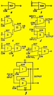
Fig. 4 - NOR unit logic functions: a - NOT unit; b - NOR unit;
c - AND unit; d - MEMORY unit; e - OR unit; f - INHIBITING GATE; g - TIME DELAY.
Note that it uses a 3-input NOR unit.
This may be the reason why many other excellent switching devices have not yet
been extensively used as industrial control systems or even for logic units.
Some of these semiconductor devices have rather startling properties, but their
cost is not low enough to compete with the common transistor.
Unijunction Switches
One of the interesting semiconductor static switches is the Unijunction transistor.
Its symbol and construction are shown in Fig. 5. It consists of a silicon bar with
a base contact at each end. An emitter junction is on the bar, somewhat closer to
base 1 than base 2. Fig. 5-b shows the basic Unijunction circuit. With no emitter
voltage applied, the silicon bar functions as a resistor, and the field created
in the bar by the current produces a small emitter-to-base voltage proportional
to the current through the bar. If the voltage applied to the emitter is less than
this voltage, the junction is reverse-biased and emitter current is minimal. When
the voltage applied to the emitter exceeds the intrinsic voltage, "holes" are injected
into the bar. They reduce the resistance of the bar between emitter and base 1.
This allows a sudden increase in emitter current. Once past this point we can decrease
emitter voltage and still increase emitter current. This gives us a negative resistance
effect. This is shown in Fig. 6, the characteristic Unijunction curve. It clearly
shows the reversal of operating mode, which we exploit as a switching characteristic.
Thus it is easy to construct a bi-stable circuit, such as a flip-flop, as shown
in Fig. 7. The trigger signal at X must be positive, or we must apply a negative
trigger at Y, to obtain the conducting state. A negative signal at X returns the
unit to the nonconducting state. Conducting resistance runs as low as from 0 to
40 ohms, nonconducting resistance as high as 1 megohm.
Many Unijunction circuits have been developed, but. no generally applied logic
units have yet been marketed. Obviously, the competition of inexpensive transistors
may hold up this development for a time.
Avalanche Diode Switching
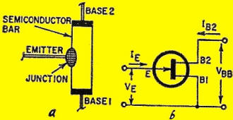
Fig. 5 - Unijunction transistor: a - construction; b - schematic
symbol.
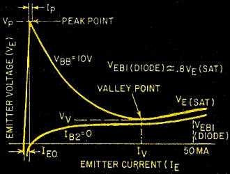
Fig. 6 - Unijunction transistor's characteristic curve shows
curve reversal that makes it usable as a switch.
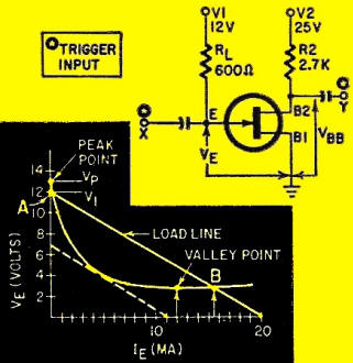
Fig. 7 - Basic Unijunction transistor bistable circuit with typical
emitter characteristic curve.
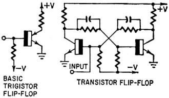
Fig. 8 - Comparison between and conventional transistor circuit.
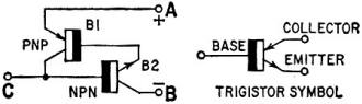
Fig. 9 - Analogy between two transistors and a Trigistor.
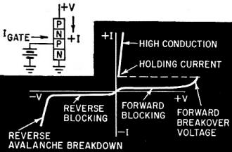
Fig. 10 - Silicon controlled rectifier and its characteristic
curve.
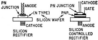
Fig. 11 - Comparing standard and controlled rectifiers.
Fig. 12 - The author's analogy for the controlled rectifier.
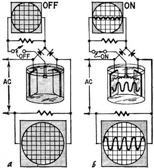
Fig. 13 - Electrochemical static switch: a -off; b - on.
We are still a long way from the bottom of the barrel. Another unusual and interesting
static switch is the avalanche switch developed by Sperry Rand. It is a diode, which
upon an increase of applied voltage switches (increases) the current through it
so rapidly that we have no way of accurately measuring the transit time, which is
on the order of a trillionth of a second. This switch uses the avalanche effect.
Some electrons, speeded up by the increased voltage, succeed in knocking a large
number of electrons out of a microscopically thin layer, creating a microplasma,
which spreads rapidly throughout the layer. This special layer is an alloy formed
by fusing a tiny speck of aluminum to a piece of silicon bar. The layer is estimated
to be four millionths of an inch thick. The diameter of the junction is slightly
over 0.001 inch!
The Trigistor
A third static switch is the Trigistor (see Fig. 8) a p-n-p-n device developed
by Solid State Products Inc. The Trigistor has the unique characteristic that it
can be turned on and off by a trigger, like any bi-stable circuit. A low-level positive
trigger applied to its base turns the Trigistor on, and it remains on without base
current. A negative trigger fed to its base turns it off, and it remains off without
base current. This makes it possible to build flip-flops with very few components.
To understand Trigistor action we look at an analogy of two transistors, a p-n-p
and an n-p-n transistor, as shown in Fig. 9. The collector of the n-p-n unit drives
the base of the p-n-p unit and vice versa. The circuit has a gain which is the product
of the betas of the two transistors. So long as these are both less than 1, the
circuit is stable with no change in current. But once this product becomes greater
than 1, regeneration keeps the process going until both transistors are saturated.
When the negative trigger is applied, the gain product once again becomes less than
1, and the transistors cut off. In the Trigistor, the two transistors are fused
into one device.
Silicon-Controlled Rectifiers
The next static switch which shows promise, particularly in the industrial electronics
field, is the silicon-controlled rectifier. This device (Fig. 10) is more analogous
to a thyratron but can also be operated as a switch, and a very good one at that.
The silicon-controlled rectifier differs from the thyratron in that a current rather
than a voltage in its control element causes conduction. Comparing the controlled
rectifier with an ordinary rectifier (Fig. 11), we see that the normal rectifier
has a silicon wafer forming the anode of the junction, while the controlled rectifier
has an n-type silicon wafer with two p-layers diffused into its surface. This combination
of p- and n-type silicon looks similar, in symbol at least, to the Trigistor. But
the effect is quite different, partly because no base junction is formed and because
the silicon wafer is just mounted on the stud.
Actually, the controlled rectifier is closer to the combination of an n-p-n transistor
and a reverse-biased diode (Fig. 12). (Let me caution the reader that this is my
own pet representation, not the manufacturer's official explanation.)
As long as the transistor is nonconducting, the voltage applied to the diode
is low, because of the resistance provided by the cutoff transistor. But when a
signal on its base makes the transistor conduct, even though the signal would be
too small to cause the reverse breakdown of the diode, the fact that the conducting
transistor now presents virtually no resistance in the circuit allows the full supply
voltage to be applied to the diode, and breakdown occurs. Once this has happened,
the voltage developed across the emitter junction would keep the transistor conducting
and the reverse pulse required to turn the thing off would, have to be as large
as the supply voltage. This is almost true. To restore the controlled rectifier
we must momentarily lower the supply drastically or bypass the rectifier. In my
analogy, you can see this would also work, for if we momentarily allowed the diode
to recover we would in effect remove the bias to the base.
The controlled rectifier has been made principally to deliver large currents.
Although a number of circuits, such as flip-flops, are based on its action as a
switch, their use in logic circuits is not immediately visualized. Where higher
current possibilities are not important, other semiconductor devices such as the
Trigistor and Unijunction transistor have definite advantages over the controlled
rectifier in terms of parts required per logic unit. Nevertheless, it is an important
type of static switch and may well find application as the final switching element
in control systems where we have heretofore been forced to use relays or contactors.
An Electrochemical Switch
A fifth static switch which we do not immediately associate with industrial control,
because its development has been directed primarily in the direction of computer
applications, is the Cryostat. In terms of construction, it is perhaps the simplest
of all. But it has some severe environmental requirements, which may hold back even
computer applications. The action of the Cryostat is based on the fact that a tantalum
wire which has been super-cooled will drastically change its resistance with a change
in the magnetic field surrounding the wire. The Cryotron operates in an open bath
of helium at approximately the boiling temperature of the liquid gas, and at room
pressure, 4.2° K. The Cryotron gate consists of about 250 turns of 3-mil niobium
wire wound on a tantalum wire, 9 mils in diameter and 1 inch long, a very small
gadget indeed. The niobium wire remains superconductive over the range of magnetic-field
change that affects the tantalum wire (a relatively small range-50 to 100 oersteds).
The change in current in the niobium wire, from 0 to about 200 ma, represents the
signal, and this changes the resistance of the 1 inch of tantalum wire from 0 to
0.008 ohm. To anyone thinking in terms of the industrial control systems we have
been discussing, this may seem like an insignificant change, hardly enough to base
a reliable control system on, until you focus again on the word zero, which is not
nearly as theoretical a word as it might seem. For superconductivity means that
a wire with a current in the superconductive state maintains this current with no
measurable decrease over a long period of time. Then the change of a fraction of
an ohm becomes relatively enormous. Many logic elements have been built, and practical
computer circuits tested. Again, the Cryostat earns its name as a static switch,
but we will not see liquid helium flasks in a factory or steel mill for some time
to come.
More likely to find application in these places is the electrochemical switch
based on a discovery by Ovshinsky of the Ovitron Corp. Fig. 13 shows this switch
diagramatically in its off and on positions. The switch, with DC on its firing electrode,
passes an AC load, and without the voltage on the electrode presents a high resistance
to the load current. No satisfactory theoretical explanation for the phenomenon
has been found. Although not likely to be a candidate immediately for a series of
AC logic circuits, this AC switch also has possibilities as the static equivalent
of relays and contactors.
Here then, besides the well developed and widely applied static switching systems,
you have seen a group of static switches, each of which may eventually come into
its own in industrial electronics, and some which are on the doorstep right now.
We have purposely avoided spending time on vacuum-tube and thyratron switching,
since they are well known devices of yesterday as well as today. Static switching
and control is today and the future. It represents a philosophy which will not only
find its way into the control phases of industry, but also into the processes we
use to produce machine parts. For example, electrolytic etching techniques are beginning
to take the whirling lathe chucks and milling cutters out of the shop and into the
museum. Not today, but certainly tomorrow, we may be producing entire machines without
much more than a few streams of liquid electrolyte moving in the plant, and then
the evolution of the process will allow us to do away even with them.
Posted July 18, 2023
|