|
January 1964 Radio-Electronics
 [Table of Contents] [Table of Contents]
Wax nostalgic about and learn from the history of early electronics.
See articles from Radio-Electronics,
published 1930-1988. All copyrights hereby acknowledged.
|
I'm no antenna expert,
so no technical contribution to author Harold Churchill's "Super Reception on Short Waves"
article will be attempted. It appeared in a 1964 issue of Radio-Electronics
magazine. Along with some suggested antenna construction techniques, he
discusses the importance of knowing how to properly aim a directional antenna in
order to hit the location for which you are targeting. Vertical angle of arrival
of radio waves is largely a function of frequency, so a generalized table is
provided there. The other angle of concern is the horizontal direction, which
relies on pointing your antenna directly at the distant target based on its
great circle bearing from your position. You cannot get that information from a
flat projection type of map. Although nowadays you simply plug the coordinates
of both locations into an online calculator, back in the day one of the handiest
tools was a good old fashioned globe. Take a piece of string and stretch it
across the sphere between you and your signal's intended destination (or
origin). The shortest path, known as the great circle path, indicates the
direction to point your antenna. The article's example is from New York City,
U.S., to Tokyo, Japan. Use this online
Great Circle Map to
view the path. Just as Mr. Churchill claims, it passes right through
Petropavlovsk, USSR (now Russia).
Super Reception on Short Waves
 By Harold B. Churchill, W2ZC, ex-W3XM By Harold B. Churchill, W2ZC, ex-W3XM
"New York to Peking - rhombic successfully overcoming
storm over Brazil! Your signals unaffected !"
Systems here include two Yagis and a rhombic "king of arrays". Complete construction details.
In the July, 1963 issue of Radio-Electronics, you read of some little known techniques
used by commercial overseas radio stations for their unusual point-to-point successes
on high frequencies. If you apply some of these to your own installation, they can
double or triple the results you're now getting using better known methods. For
instance, I suggested a simple replacement for the conventional horizontal dipole
antenna (July, page 20) that multiplies long-distance results many times - its extra
cost, about $3.
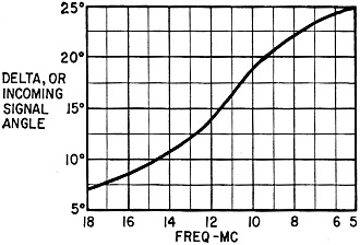
Fig. 1 - Vertical angles of incoming trans-Atlantic signals.
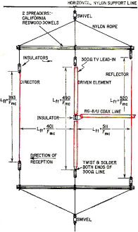
Fig. 2 - Vertical Yagi swivels for aiming in any direction. Element
lengths and spacings must be computed for particular band. Gain is about 8.6 db
over straight horizontal dipole.
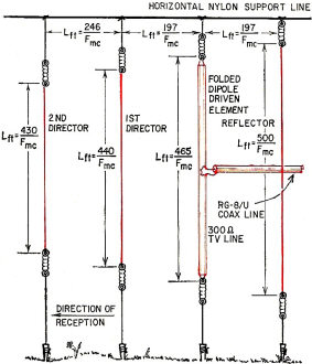
Fig. 3 - Four-element vertical is too big to rotate, but may
be "steered" vertically by raising and lowering horizontal support. Lengths and
spacings are figured from formulas. Gain, about 9.5 db over reference horizontal
dipole.
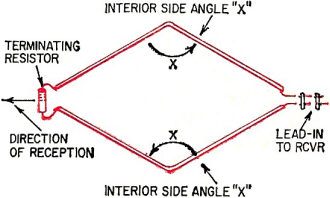
Fig. 4 - Bird's-eye view of rhombic. All sides and opposite angles
are equal. Terminating resistor is at far end, in direction of reception. See tables
for dimensions and angles.
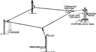
Fig. 5 - Layout of a rhombic. Counter-balancing permits "stretching"
antenna with hand or motor winch, to accommodate different wave angles.
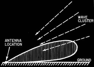
Fig. 6 - Rough representation of narrow vertical lobe of rhombic
system. By altering interior angles, as in Fig. 5, antenna is steered to select
best reception.

Fig. 7 - 800-ohm terminating resistance is made up of two 430-ohm
noninductive resistors in series. Series connection reduces wet-weather leakage.
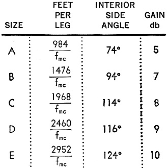
Table I - Figure your size rhombic. Note: All sides same
length, calculated from formula in column 2. Gain is stated as db over dipole performance at dipole's resonant frequency.
Since rhombic is nonresonant, improvement is even greater at other frequencies.
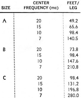
Table II - Actual sizes of three smaller rhombics at four
frequencies.
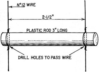
Fig. 8 - Details of 490-ohm matching section. Use polystyrene
rod if available. Hold spacers in place with short bits of wire twisted around
line wires as shown.
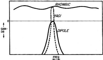
Fig. 9 - Comparative performance of simple dipole, Yagi and rhombic.
Yagi, though sensitive and highly directive, is even less broad-banded than dipole.
Rhombic has as much gain over wide range as Yagi at resonance.
Because it's one of the little-known keys to successful distance reception, Fig.
1 is reprinted from the July story. It shows the vertical angles at which signals
cross the Atlantic between our East Coast and Europe.
The comparatively elementary antennas in the July article receive equally well
in all compass directions. But each has strong vertical gain built into its design.
Therefore they work as well between Los Angeles and Honolulu as between New York
and London without any change. Cut them to the right length, support them properly
and off they go.
The next step in powerful reception is high-gain antennas that concentrate reception
in both the horizontal and vertical planes. These are counterparts of a radiotelescope
that aims at its target in azimuth and elevation.
Horizontal Aiming
This is simple once you understand a few basic facts, but can be misleading unless
you do. Keep this in mind: with a few erratic exceptions when the earth's magnetic
lines alter their courses, all overseas radio signals arrive by great circle routes.
For instance, if you live in New York and wish to hear Tokyo, don't aim your beam
via San Francisco, but right across Petropavlovsk, USSR, at 335°. So the common
Mercator projection is less than useless. Of course, special azimuthal maps for
radio use can be purchased, but they're available only for a few locations in the
US and are in error for any others.
The ideal instrument for finding radio directions rapidly is the new but special
and inexpensive globe designed by the National Geographic Society of Washington
D.C. and available at larger stationery stores. With it, it's possible to aim any
of the powerful beams presented in this article. It works for any location on the
globe.
The first beam is shown in Fig. 2. Vertical suspension greatly increases its
long-distance capability. (Note the very low incoming angles in Fig. 1.) It is a
vertical adaptation of the Yagi, so widely used for TV reception, but re-oriented
for short wave distant reception. The carefully chosen spacing between its reflector,
driven element and director broad-bands its operation across any cluster of overseas
stations. If supported by horizontal spreaders (use light California redwood), it
can be rotated horizontally in any direction, as indicated by the National Geographic
globe. So it applies its gain at any part of the world simply by rotation. It can
be readily steered in the vertical plane by changing its height above ground, by
altering tension on the horizontal supporting rope. The receiver S-meter indicates
at once what height is best under any conditions.
The performance of this vertical Yagi is greatly improved by laying a ground-screen
directly under it. Completely satisfactory ground-screen wire can be bought cheaply
at a scrap-metal yard and need be buried only an inch or so under the ground surface.
A garden edger is a good tool for this. After the first rain, there's no sign that
a ground-screen is under a lawn.
The ground-screen wires should be soldered together, and a ground stake driven
in at their center. No connection is needed to the antenna proper or to the receiver.
It acts as a near-perfect reflecting area.
Still More Pull
A still more powerful version of this vertical Yagi is shown in Fig. 3. It contains
a greater number of elements to increase its gain. This more powerful version is
somewhat too long to rotate. Its elements are simply dropped from a horizontal support
line made from small-gage nylon rope.
The aiming is determined by the direction of the support line.
As in all long-distance vertical arrays, a ground screen helps greatly. For this
longer array, the screen should extend in crow-foot fashion as far as possible in
the direction of the incoming signals. The longer this crow-foot configuration,
the louder the signals. Tests show improvement is still taking place as these wires
exceed 100 feet.
This very large vertical array may also be steered in the vertical plane the
same way its smaller counterpart is - that is, by altering its height above ground.
In this case, a system of pulleys permits the entire support line to be raised or
lowered, and an indication of optimum for any given day will at once be readable
on the receiver S-meter.
Since the vertical and horizontal concentration of this high-gain beam is exceedingly
strong, it should not be oriented toward a nearby source of noise (a factory, a
building using neon signs, or electrical machinery). Its receptivity will skirt
the ground by some 100 in the vertical plane, and will not clear noise-producing
equipment for some distance in its target direction.
The Rhombic Antenna
The rhombic is the undisputed king of arrays by a very large margin. It is the
mainstay of modern commercial overseas reception and, built on a smaller scale,
the proud possession of a few advanced short-wave listeners and radio amateurs.
There are three good reasons for its supremacy: its gain, broad-band reception,
and, when properly terminated (resistor connected across its far-end apex), the
fact that it can more than double signal-to-noise ratio.
Because of this top-flight performance, it is the basic element in the world's
most powerful receiving antenna, the MUSA (Multiple Unit Steering Array) of the
American Telephone & Telegraph Co. The MUSA is made up of a succession of rhombics
in a line aimed at a transoceanic target. By altering the phase relationship between
these rhombics, the vertical angle of reception is automatically steered for top
overseas reception at any moment.
The next antenna in this series presented by Radio-Electronics is the direct
predecessor of MUSA. If you have enough space for it, you can put it up for very
little cost, considering the results obtained.
The main requirement is four poles (or four trees if they're in the right spots).
The rhombic antenna is easy to visualize. Glance at its diamond shape in Fig.
4. It receives in a direction away from its lead-in. As a transoceanic signal arrives,
it strikes this diamond configuration, whose parts add together all received energy
in the right phase and pass it on to the receiver through the lead-in.
There are three simple rules about the rhombic: the larger it is, the greater
its gain; the higher you can erect it, the better, and, for each size, there are
optimum interior angles that turn out best results.
The first question you will ask is, "Do I have enough room for a super-power
rhombic?" Answer it by making a small-scale drawing on paper, and seeing what sizes
can fit on the space available. Tables I and II help compute this rapidly with a
ruler and protractor.
Approach it this way: decide which overseas band is of most interest to you (where
the antenna's top performance will be centered), and then draft up a scale drawing
or two. Fitting the space you have, you can choose size A, B, C, D or E. Each is
progressively more powerful. For instance, to see how size A fits into the space
you have, divide the frequency of your preferred overseas band into 984. This gives
you the number of feet you will need in each leg of the diamond shape. The third
column of Table I shows your interior side angles will each be 74°. Construct
these dimensions in a small-scale drawing, and right away you'll see the space you
need.
Putting up a Rhombic
Fig. 5 shows the physical layout of a typical rhombic. While poles are shown
here for simplicity, trees will serve very satisfactorily if they are at or near
the right spots. At least three such antennas erected in wooded areas on the East
Coast are performing excellently for very strong transoceanic reception. Signal
attenuation by foliage is not too serious at overseas-broadcast frequencies.
Pulleys and weights are used at the side apexes of the rhombic, and a pulley
and hand winch at its end. A more simple system could replace the winch. By increasing
or decreasing the pull on the far-end rope, the interior angles of the rhombic are
increased or decreased, steering reception in the vertical plane.
How this works for reception is shown in Fig. 6. The receiving lobe (or vertically
aimed pattern) can be moved up or down to receive the incoming wave clusters carrying
the loudest signals. The rhombic receives at its lowest angles (best for extreme
distance) when the far-end rope tension is lessened and the side angles of the diamond
shape are smallest. Careful measurements show a typical test rhombic can be steered
from 5° up to 17° in the vertical plane by a 28° change in its side
angles. This is considerable vertical steerage, and can accommodate a wide variety
of conditions.
Termination and Lead-In
For best performance, these rhombics should be terminated at their far end (which
points at the target). This is readily done by using two small 430-ohm carbon resistors,
attached as in Fig. 7. These two resistors total approximately 800 ohms, which matches
the impedance of the single-wire rhombic. They serve a very important purpose: they
cause the rhombic to receive only in the forward direction - that is, in the direction
of the target. This termination does two other things: it greatly reduces atmospheric
noise pick up, and broad-bands the antenna's response.
The proper lead-in for an 800-ohm rhombic generally presents a problem. An open-wire
800-ohm line (coaxial line will not work) requires a spacing of nearly 15 inches
between the two wires, so the line itself would start to receive noise and unwanted
signals from the wrong direction.
A highly practical way to beat this problem is to use a short open-wire section
of 490-ohm line between the near end of the rhombic and standard 300-ohm TV line
which can then serve as 95% of the lead-in. This simple system provides a perfect
match at the preferred overseas band, and still functions very well indeed on adjacent
over-seas bands. This short open-wire section is at the geometric mean impedance
between the 800-ohm rhombic and the standard 300-ohm TV line.
The matching section is made of two parallel No. 12 wires spaced 2 1/2 inches
by small plastic rods (see detail in Fig. 8). The length of this matching line (in
feet) will be 246 divided by the frequency in megacycles of the preferred overseas
band.
It's Worth It
Fig. 9 compares the rhombic, Yagi and dipole. But, to appreciate the performance
of the rhombic, you have to listen on one. I still recall my first experience. As
a visitor to the Bell Telephone Laboratories antenna test site some time ago, I
asked if I could tune the Bell receiver-fed by a rhombic - from the incoming overseas
telephone channel to the European broadcast band for a moment. The experience was
at first unbelievable. Signals from the major European capitals were indistinguishable
in static-free volume from local US stations, they came in so powerfully. I could
only grasp what I was hearing when the stations identified themselves.
Some time later, I erected my own smaller rhombic for 14-mc (20-meter) amateur
transmission to Europe. My signals were at once reported more than twice as loud
as competing US stations not using rhombics.
When you erect your rhombic, you'll notice that transoceanic signals come in
far earlier than on any other antenna, and their volume stays high far later. Your
reception time will be greatly increased. There is surprisingly little static compared
to a simple dipole, because the rhombic dissipates in its terminating resistance
atmospheric noise coming in from its reverse direction. This is very noticeable
on the trans-Atlantic run between New York and Europe where the terminated rhombic
eliminates static arriving from Mexico in the opposite direction. And you soon notice
the difference over the New York to Far East circuit. Storms over the South American
jungles of Brazil and Argentina normally vie with incoming signals from Manila,
Tokyo and Peking, when using a simple antenna. They don't with a rhombic.
Posted January 12, 2023
|