|
November 1961 Radio-Electronics
 [Table of Contents] [Table of Contents]
Wax nostalgic about and learn from the history of early electronics.
See articles from Radio-Electronics,
published 1930-1988. All copyrights hereby acknowledged.
|
As mentioned
previously, my professional electronics career began with the U.S. Air Force in
late 1978. As an Air Traffic Control
Radar Repairman (AFSC 303x1), the first phase of training was basic
electronics, and a short course on proper soldering techniques. A lot of
emphasis was placed on removal of the faulty component without damaging its
environment (circuit board, point-to-point chassis connections, etc.), and then
to properly install the new component, also without damaging the environment. We
learned about forming component leads so as not to stress them mechanically,
orientation and placement, cleaning the connections both before and after
soldering, and then soldering technique. We also learned how to repair circuit
boards (only singe and double sided). As shown in this 1961
Radio-Electronics article entitled "Technician's Guide to Good Soldering,"
there is a preferred way to tin component and wire, a preferred way to form the
leads and wires, and a preferred way to apply heat and solder to the joints.
That class lasted maybe two days. Four years later after getting hired as an
electronics technician at the Westinghouse Oceanic Division, the first thing I
did was attend a two week soldering class to be certified to NASA level
soldering, since I would be building MIL-SPEC electronics assemblies (primarily
sonar systems). I built everything from torpedo sonar transducer arrays to
circuits boards and chassis assemblies. I also built many very complicated cable
harnesses for both sonar and radar systems. It was very interesting work, since
the area I worked was not a high volume environment, usually involving from one
to maybe a dozen of any given product. Navy inspectors scrutinized every solder
joint (and mechanical items) we made, often using an eye loupe or a microscope.
It was very demanding.
Technician's Guide to Good Soldering
 By H. W. McMurtray* By H. W. McMurtray*
Every skilled operator takes pride in the excellent workmanship and sure attainment
of high standards that result from his own effort and ability. But, to encourage
him to do his best work, the industrial technician must have reliable and precise
information that plainly describes the standards of quality required of his product.
Mutual recognition of and agreement on these standards by instructors, operators
and inspectors alike is essential.
These illustrations, excerpted from a forthcoming Raytheon booklet, have been
prepared as a guide toward better recognition of required standards for light assembly
soldering operations. They are actual photographs of various types of joints, together
with comments that illustrate the difference between good and bad solder joints.
The method of heat transfer used in these examples is the common electric soldering
iron. There are a number of other available methods, including the induction heating
device, the resistance heating medium, the heating oven and the open flame torch.
These instructions are applicable in general to all methods. When followed, they
will result in reliable solder joints.
 We hope that these examples will help to
demonstrate what constitutes a reliable and usable soldering joint, and to eliminate
differences and discussions between technicians, inspectors and others. We hope that these examples will help to
demonstrate what constitutes a reliable and usable soldering joint, and to eliminate
differences and discussions between technicians, inspectors and others.
***
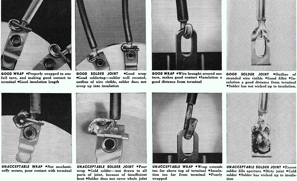
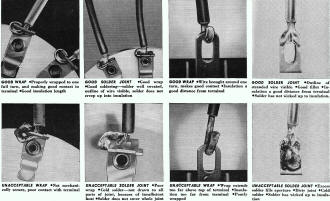
Wafer Switches
Good Wrap | Properly wrapped to one full turn, and making
good contact to terminal | Good insulation length
Good Solder Joint | Good wrap | Good soldering - solder
well sweated, outline of wire visible, solder does not creep up into insulation
Unacceptable Wrap | Not mechanically secure, poor contact
with terminal
Unacceptable Solder Joint | Poor wrap | Cold solder - not
drawn to all parts of joint, because of insufficient heat | Solder does
not cover whole joint
***
 Solder Terminals Solder Terminals
Good Wrap
| Wire brought around one turn, makes good contact | Insulation a good
distance from terminal
Unacceptable Wrap | Wrap extends too far above top of
terminal | Insulation too far from terminal | Poorly wrapped
Good Solder Joint |Outline of stranded wire visible | Good
fillet | Insulation a good distance from terminal | Solder has not wicked
up to insulation
Unacceptable Solder Joint | Excess solder fills aperture |
Dirty joint | Cold solder | Solder has wicked up to insulation
Pitfalls to Avoid
1. Don't attempt to solder with an iron if the tip is not clean.
2. Don't allow excess solder on the tip of the iron before contact is made
with the mechanical assembly.
3. Don't remove the iron from the assembly before solder has been drawn
to all parts of the joint.
4. Don't allow wire or other parts of the joint to move before solder has
solidified.
5. Don't attempt to solder a heavy assembly with a small iron.
6. Don't attempt to improve a poor mechanical assembly with a good solder
joint.
Photography by Salinger & Enneguess Advertising, Boston, Mass.
***
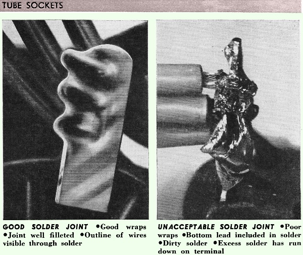
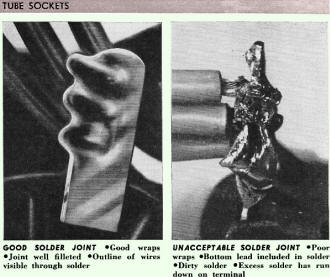
Tube Sockets
Good Solder Joint |Good wraps |Joint well filleted
-Outline of wires visible through solder
Unacceptable Solder Joint | Poor wraps | Bottom lead
included in solder | Dirty solder | Excess solder has run down on terminal
***
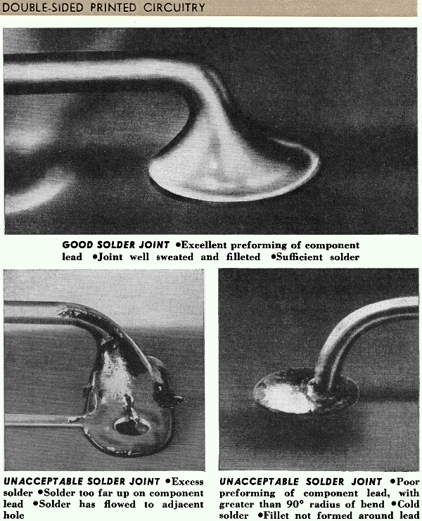
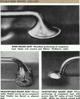
Double-Sided Printed Circuitry
Good Solder Joint | Excellent preforming of component lead |
Joint well sweated and filleted | Sufficient solder
Unacceptable Solder Joint | Excess solder fills aperture |
Dirty joint -Cold solder | Solder has wicked up to insulation
Unacceptable Solder Joint | Excess solder | Solder too far
up on component lead | Solder has flowed to adjacent hole
Unacceptable Solder Joint | Poor preforming of component
lead, with greater than 90° radius of bend | Cold solder - Fillet not formed
around lead
*Manager, quality control, Airborne Manufacturing, Raytheon Co.
Posted July 19, 2024
|