New Sound Recording System
|
|
John Potter Shields celebrated in his Pittsburgh Sun Telegraph hometown newspaper. It mentions his cover feature in this issue of Radio-Electronics magazine. John Potter Shields was somewhat of a prolific author of technical books, primarily on the subjects of electronics and amateur astronomy - both of which are interests of mine. This "New Sound Recoding System" article from a 1952 issue of Radio-Electronics magazine reported on a system he devised for writing audio to a photographic plate in a manner similar to a record engraving on a platter. He places an unexposed film plate in front of a cathode ray tube (CRT) and modulates the beam with audio, which is superimposed on a deflection plate signal that moves the beam (cathode ray) in a spiral of fine spacing from the outside edge of the CRT in toward the center - just like a record (both shellac* - the kind Moe would break over Curly's head - and vinyl). * See this amazing c1942 RCA video showing how shellac records were made. Note the nearly total absence of safety devices on machinery or on operators. I also notice an absence of visual inspection for surface flaws or contamination during the master production process, which may have been done but not shown. Interestingly, the record labels are added prior to the hot pressing. As with so many high tech products, the amount of manual labor involved was immense. Now, those old records still surviving can be found in thrift stores selling for mere pennies (in inflated dollars). New Sound Recording System - Cover Story
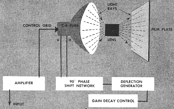
Without moving parts, this all-electronic system combines the techniques of sound-on-film and disc recording. Spiral scanning of an intensity-modulated cathode-ray beam records 30-minute programs on discs of ordinary photographic film. Standard commercial components are used. By John Potter Shields The writer has developed a new system of sound recording and reproduction which is believed to be a definite advance in this field. Fig. 1 is a block diagram of the recording system. It operates as follows: The cathode-ray tube generates a beam of electrons which produces a movable spot of light on its screen. This movable spot of light is focused by the lens onto the unexposed film plate. The output of the amplifier is connected to the control grid of the cathode-ray tube so that its bias will vary in accordance with the audio frequency variations applied to the amplifier's input. As the bias on the cathode-ray tube is varied, the brightness of the spot of light will vary; therefore the intensity of the spot of light will vary in accordance with the audio signal applied to the input of the amplifier. This so far stationary spot of light is deflected by the following means: The deflection generator produces a 40 c.p.m. sine-wave output which is applied to the 90-degree phase-shift network. This splits the output from the deflection generator into two parts which are equal in frequency and amplitude, but differ in phase by 90 degrees. The two outputs from the phase-shift network are applied to the vertical and horizontal deflection plates of the cathode-ray tube. The above-mentioned spot of light will now form a circular trace, or more exactly the spot of light will rotate at a speed of 40 r.p.m. By varying the gain of the deflection generator linearly from maximum to minimum, the rotating spot of light will travel in a spiral toward the center of the cathode-ray tube screen. By properly varying the gain decay time of the deflection generator, very close spacing may be obtained between adjacent turns of the spiral trace.
Fig. 1 - Block diagram of the all-electronic recording system. Special oscillators in the deflection genera tor produce the low scanning frequencies required.
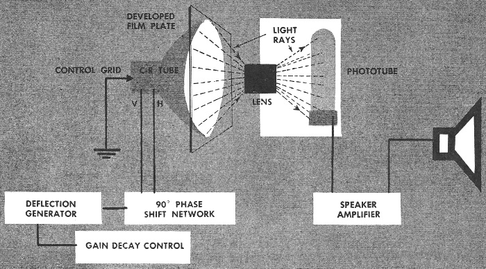
Fig. 2 - Light from an unmodulated cathode-ray beam scans the developed film in the reproducing setup. The scanning circuits are identical to those used for recording. Thus it can be seen that the developed film plate will consist of a spiral trace with very close spacing between adjacent turns on the spiral. Each line of the spiral will consist of varying light and dark areas which correspond to the audio-frequency variations applied to the input of the amplifier. A little more than 30 minutes of recorded material can be placed on a single 12-inch disc. In the development of this new sound recording system, several rather large problems had to be solved. For example, a suitable oscillator had to be chosen for the deflection generator. The conventional L-C oscillator naturally would be of no use here, as the values of inductance and capacitance required for operation at 40 c.p.m. would be much too large to be practical. Several types of R-C oscillators were tried and the circuit that was finally chosen was the phase-shift oscillator. This type of circuit requires only one tube; it is extremely stable; relatively small values of resistance and capacitance are required for its operation at 40 c.p.m.; and when properly adjusted it is capable of almost pure sine-wave output. The type of 90-degree phase-shift network used requires a balanced input, so a modified cathodyne phase inverter is used for this purpose. The development model of the all-electronic recording and playback system. The outputs from the 90-degree phase-shift network are fed to two push-pull deflection amplifiers whose outputs are connected to their respective sets of deflection plates. Modified R-C amplifiers are used throughout this system, as they were found to be as satisfactory in this case as direct-coupled amplifiers. An r.f. voltage-doubling power supply is used with the cathode-ray tube to provide maximum brightness and sharpness of focus. The type of cathode-ray tube used in both the recording and reproducing systems is a type 10HP4. When work was first started on this system it was planned to use a type 10BP4, as it has an almost flat face, and a higher second-anode voltage can be applied to it than to an electrostatic tube. The deflection amplifiers obviously could not be connected to the deflection yoke by a transformer, due to the extremely low frequencies involved. Cathode-follower coupling circuits were tried with little success, due to the low resistance of commercially available yokes. It was also found that the direct current flowing in the yoke caused excessive deflection of the electron beam. Thus the type 10HP4 was chosen. It was found that more second-anode voltage could be applied than had been expected. Naturally as the second-anode voltage is increased, greater deflection voltage is required due to the increased stiffness of the beam. The type P4 phosphor is satisfactory, as its decay characteristics are sufficiently rapid to allow its use at the commonly employed audio frequencies. A small amount of high-frequency equalization was used to produce output flat from 20 to 20,000 cycles from the photocell. If a tube with a short-persistence phosphor, such as type P11, were used, no equalization would be required. The photograph shows the equipment used by the writer in developing this system. On the extreme left is an audio-frequency oscillator. Next to it is the chassis containing the phase-shift oscillator, control circuit, 90-degree phase-shift network, and the push pull deflection amplifiers. The tuning eye on this chassis is for adjusting the phase-shift oscillator for optimum sine wave output. Behind this chassis is the r.f. power supply, and to their right is the 10HP4 cathode-ray tube. In front of it is the shield box containing the photocell used for reproduction. Reproduction The recording process has to be reversed for reproduction. In Fig. 2 is shown a cathode-ray tube identical to the one in the recording system. A beam of electrons is generated within the cathode-ray tube, producing a spot of light which is focused by the lens onto the photocell. The deflection generator and 90-degree phase-shift network are identical to those used in the recording system. The control grid of the reproducing cathode-ray tube is grounded and thus maintained at a fixed potential to keep the spot of light on the cathode-ray tube at a fixed intensity. As in the case of the recording system, a spiral trace will be produced on the reproducing cathode-ray tube. It will be identical to the trace on the recording tube, as the same type of deflection generator and 90-degree phase-shift network is used in each case. The film plate, on which audio frequency sounds were recorded, is now developed and placed between the face of the cathode-ray tube and the lens so that the spiral trace recorded on the developed film will correspond to the spiral trace on the reproducing cathode-ray tube. As the spot of light - maintained at a constant intensity - travels spirally toward the center of the screen of the cathode-ray tube at the same speed as the recording spot of light, it will pass through the varying light and dark areas of the film and strike the photocell. The light of varying intensity striking the photocell causes corresponding voltage variations from the photocell. These voltage variations will be an exact facsimile of the audio-frequency variations applied to the recording system amplifier's input. The output from the photocell is then amplified and applied to a suitable loudspeaker. It is apparent that many advantages are to be gained by use of the Shields recording and reproducing system. In the first place, this system does not require motors or mechanical drive systems, and so far as is known (a thorough patent search was made before applying for patents), it is the first recording and reproducing system which is entirely electronic in operation. Many advantages are to be gained by this. It is extremely difficult to design and produce mechanical drive systems which operate properly at the low speeds which are required for recording work. Wow and flutter are two factors which must be contended with, and as the speed is reduced these factors become more prominent. With this all-electronic system it is an easy matter to have the spot of light rotate at extremely low speeds with the phase-shift oscillator in the deflection generator. Trouble with wow or flutter disappears as the phase-shift oscillator is very stable. If extreme spot rotation stability is required (as might be the case in laboratory work) there are various R-C oscillator circuits which will operate at these low frequencies, and which can be readily synchronized. Precise control can be maintained over the deflection generator and its associated circuits. This system does not require any mechanical movement of the recording medium. Thus there will be no deterioration of the recording medium, as it is stationary and is contacted by nothing heavier than a beam of light. Hence it will last indefinitely. There is also little chance of it collecting dust particles, as there is no friction caused by mechanical movement to attract dust. Inexpensive copies can be easily made of the original developed film plate. This recording medium is small in size and light in weight; thus it can be conveniently stored. By employing cathode-ray tubes in the recording and reproducing systems which produce traces of extremely small diameter, considerable sound (or other types of data that can be expressed in electrical form) can be recorded on a single film plate. Although not mentioned in this article, the writer has developed methods to automatically select any portion of the recording for reproduction. This would be useful in coin-operated machines where it is desired to play only one musical selection out of several which were recorded. By simply pressing a button, the proper selection can be chosen without need of rather complicated mechanical means. This system is simple in design and construction considering the advantages to be gained by its use. Only a few of its advantages have been cited in this article; others will become apparent to the reader.
Posted May 6, 2022 |
|