|
April 1960 Radio-Electronics
 [Table of Contents] [Table of Contents]
Wax nostalgic about and learn from the history of early electronics.
See articles from Radio-Electronics,
published 1930-1988. All copyrights hereby acknowledged.
|
Using modern blazing
speed computers and sophisticated programs, designing and analyzing something as
complex as a spiral conical antenna is child's play - and many school-age
children actually do it. It wouldn't surprise me if there is a phone app
capable of performing such tasks. However, back in 1960 when this article
appeared in Radio-Electronics magazine, a lot of intuition, guesswork,
and trial and error on physical models was necessary to model and parameterize
the spiral conical antenna shown on the cover. This particular antenna resonates
at 14 MHz with a 1.25:1 VSWR, however across the 7-17 MHz intended bandwidth the
VSWR can be as high as 6:1. Surprisingly, an image search for spiral conical
antenna radiation patterns did not turn up much. This paper from the
International Center for Radio Astronomy Research is about the best I could
find. Maybe there is so little interest in spiral conical antennas that nobody
bothers analyzing them.
Spiral Conical Antenna - Cover Feature

Cover Feature: Spiral Conical Antenna
By W. W. Macalpine*
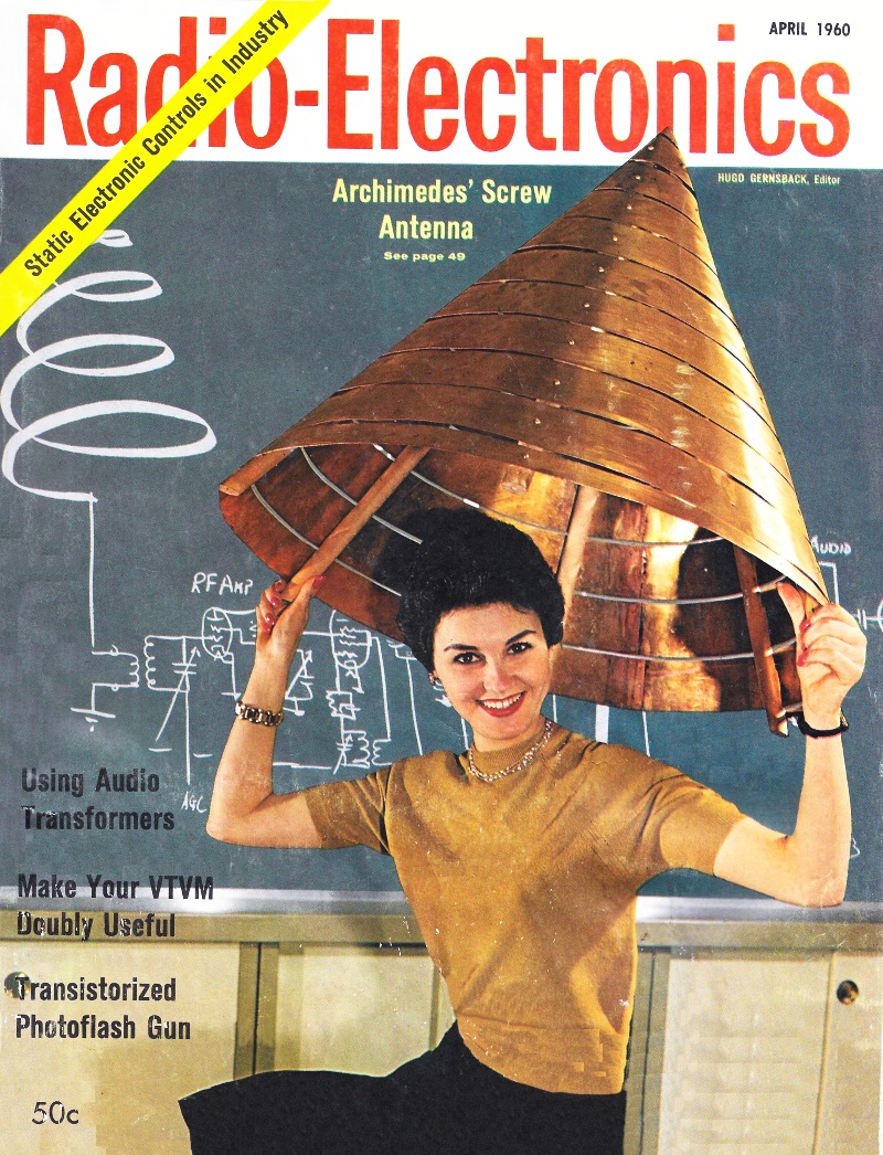
The antenna on this month's cover, although conceived early in 1959, is not yet
a finished development. It was built to see how such a design might perform. There
haven't been enough tests to give any conclusive results.
The cone is made of thin sheet brass cut into a conical version of the Archimedes
spiral. It is cut from a flat semi-circular sheet and formed around a pyramidal
frame consisting of six insulating rods. (The brass would be silver- or copper-plated
in a finished model.) The slant cone has a 30-inch base diameter, 30-inch slant
height, 26-inch axial height and a 60° apex angle. There are 10 turns on the
spiral. An earlier model had the same cone dimensions, but only a five-turn spiral
of 6-inch-wide brass.
The later model has undergone a few tests. It was mounted with its cone axis
vertical to give an omnidirectional pattern in the horizontal plane. A horizontal
conducting plane was set up close to the cone's apex. The plane was a brass disc,
sometimes cut into a left-or right-hand spiral and at other times an uncut sheet.
Feed was by coaxial cable connected between the plane and the spiral's apex; ground
to the spiral and center conductor to the disc, or vice versa. This drive resembled
that of the "discone" antenna (see Reference Data for Radio Engineers, fourth edition,
page 681). However, he spiral cone was not likely to have the broadband characteristic
of the discone, since he aperture of the spiral antenna is small compared to the
free-space wavelength at the lowest frequency of resonance.
The five-turn spiral cone had a resonance at 14 mc with a voltage standing-wave
ratio (VSWR) of 1.25 to 1 on a 50-ohm line. A test with a transformer of 4-1 impedance
ratio (step-up to spiral) gave SWR a little under 6 to 1 on a 50-ohm line over the
entire range of 7 to 17 mc. The impedance plot was roughly a circle about one and
one-half times around, on the Smith chart.
Other drive systems are possible, such as shorting the apex of the cone to the
plane and driving between the apex and a tap on the cone. Another system would use
two cones on the same axis with adjacent apexes as in the biconical antenna. Drive
would be balanced feed to the apexes, or to taps on the cones if the apexes are
shorted.
* Development Engineer, ITT Labs.
Posted February 6, 2023
|